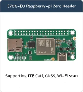

LTE Raspberry Pi Hat
Basic Overview #
The LTE Raspberry Pi HAT is a compact and fully integrated cellular communication board designed to add LTE connectivity to Raspberry Pi-based systems with minimal hardware complexity. This board combines LTE networking, GNSS support, RF interfaces, SIM card management, and power handling into a single embedded platform, making it highly suitable for industrial IoT, remote monitoring, telemetry, smart automation, and edge computing applications.
Unlike traditional cellular designs that require separate RF layout, antenna matching, SIM circuitry, voltage regulation, and communication interfaces, this HAT significantly simplifies the development process by providing a ready-to-use hardware solution compatible with the standard Raspberry Pi GPIO architecture.
The board is mechanically and electrically designed around the Raspberry Pi Zero / Raspberry Pi 40-pin header standard, allowing direct integration with various Raspberry Pi models without requiring additional interface converters or custom carrier boards.
Supported Module List #
The pin of this board are standard Raspberry pi zero bases.
Feature List #
- Supports FDD-LTE and TDD-LTE networks
- Class 3 transmit power (23 dBm ±2.7 dB) for both FDD-LTE and TDD-LTE bands
- Maximum support for LTE CAT-1 Bis (single-antenna design)
- Supports 1.4 MHz to 20 MHz RF bandwidth
- Data rates:
- FDD-LTE:
-
-
- Maximum downlink rate up to 10 Mbps
- Maximum uplink rate up to 5 Mbps
- TDD-LTE:
-
-
-
- Maximum downlink rate up to 8 Mbps
- Maximum uplink rate up to 2 Mbps
-
- Supports Wi-Fi Scan positioning, sharing the main antenna
- Supports multiple network protocols:
- TCP / UDP / MQTT / FTP / FTPS / HTTP / HTTPS / LWM2M / CoAP
- PCM interface for audio applications, requires an external audio codec
- Supports 16-bit linear audio encoding format
- Supports Short Frame Mode: the module operates only as a master device
- Supports USB 2.0 for AT commands, data transmission, and firmware upgrade
- Supports UART interface with hardware flow control (RTS/CTS)
- Supports USIM/SIM cards (1.8 V and 3 V)
Board Resources #
Function Description #
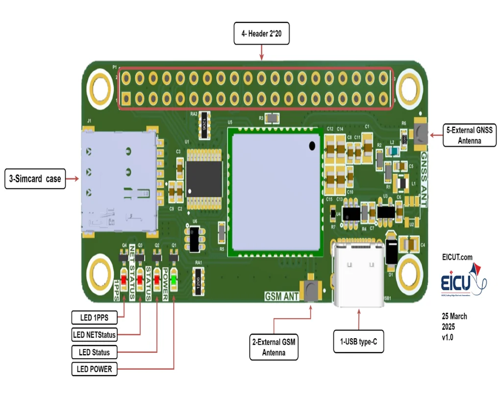
The detailed assignment of the peripheral interfaces on the Raspberry pi hat is as follows:
| NO. | Name | Silkscreen | Comment |
|---|---|---|---|
| 1 | USB Type-C | USB1 | – |
| 2 | External GSM Antenna | GSM ANT | UFL ANTENNA |
| 3 | Sim card case | J1 | 4FF SIM Card 12.3* 8mm |
| 4 | Pin header 40 pin | P1 | 2*20 PIN 2.54 |
| 5 | External GNSS Antenna | GNSS ANT | UFL ANTENNA |
The Raspberry pa hat board has 4 functional indication LEDs, as follows:
- D1: 1PPS LED
- D2: Netstatus LED
- D3: Status LED
- D4: Power LED
Board Interfaces #
The main pin placement of the Raspberry pi hat board is shown in the following figure:
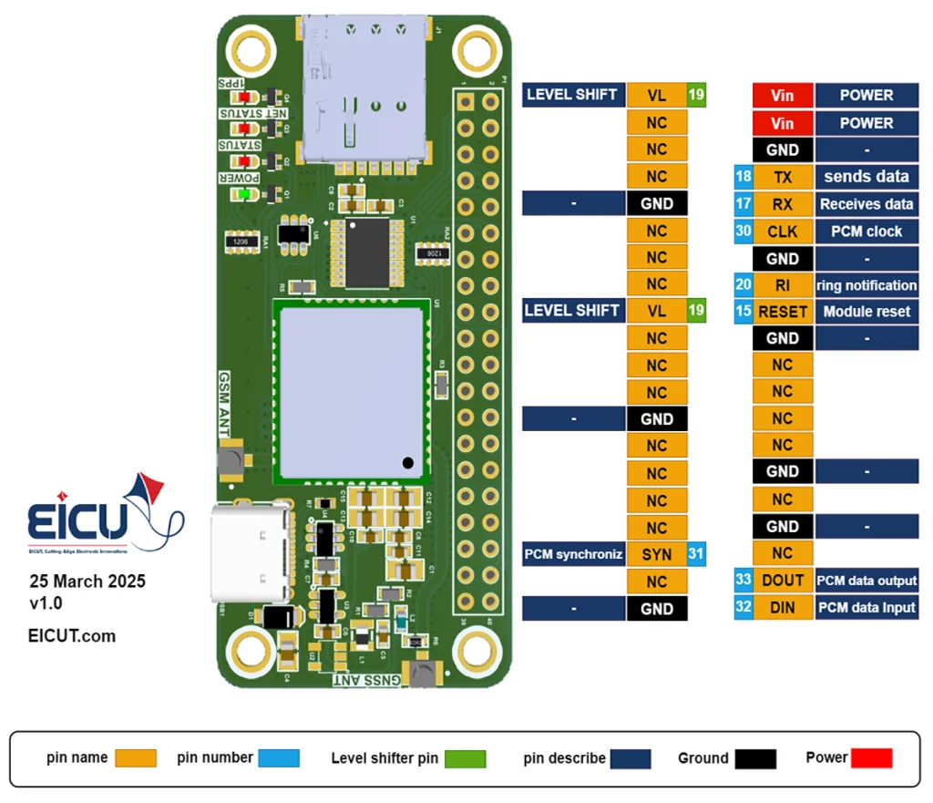
LTE Raspberry pi hat P1:
| NO. | Name | Silkscreen | Comment |
|---|---|---|---|
| P1-1 | LEVEL SHIFT VOLTAGE | VL | The voltage that shifts the pins to that level. (for raspberry connect to 3.3V) |
| P1-2 | POWER | VIN | Ensure that the power supply can provide sufficient current during a transmission burst, which can peak at 1.6 A. The supply voltage should remain within Vmin = 4.5 V and Vmax = 5.5 V. |
| P1-3 | Not connect | NC | – |
| P1-4 | POWER | VIN | Ensure that the power supply can provide sufficient current during a transmission burst, which can peak at 1.6 A. The supply voltage should remain within Vmin = 4.5 V and Vmax = 5.5 V. |
| P1-5 | Not connect | NC | – |
| P1-6 | Ground | GND | – |
| P1-7 | Not connect | NC | – |
| P1-8 | TXD | TX | Transmit data |
| P1-9 | Ground | GND | – |
| P1-10 | RXD | RX | Receive data |
| P1-11 | Not connect | NC | – |
| P1-12 | PCM clock signal | CLK | The default GPIO can be configured as a PCM interface. |
| P1-13 | Not connect | NC | – |
| P1-14 | Ground | GND | – |
| P1-15 | Not connect | NC | – |
| P1-16 | RI | RI | Ring indication |
| P1-17 | LEVEL SHIFT VOLTAGE | VL | The voltage that shifts the pins to that level. (for raspberry connect to 3.3V) |
| P1-18 | Module reset | RESET | Active low |
| P1-19 | Not connect | NC | – |
| P1-20 | Ground | GND | – |
| P1-21 | Not connect | NC | – |
| P1-22 | Not connect | NC | – |
| P1-23 | Not connect | NC | – |
| P1-24 | Not connect | NC | – |
| P1-25 | Ground | GND | – |
| P1-26 | Not connect | NC | – |
| P1-27 | Not connect | NC | – |
| P1-28 | Not connect | NC | – |
| P1-29 | Not connect | NC | – |
| P1-30 | Ground | GND | – |
| P1-31 | Not connect | NC | – |
| P1-32 | Not connect | NC | – |
| P1-33 | Not connect | NC | – |
| P1-34 | Ground | GND | – |
| P1-35 | PCM frame synchronization | SYN | The default GPIO can be configured as a PCM interface. |
| P1-36 | Not connect | NC | – |
| P1-37 | Not connect | NC | – |
| P1-38 | PCM data output | DOUT | The default GPIO can be configured as a PCM interface. |
| P1-39 | Ground | GND | – |
| P1-40 | PCM Data Input | DIN | The default GPIO can be configured as a PCM interface. |
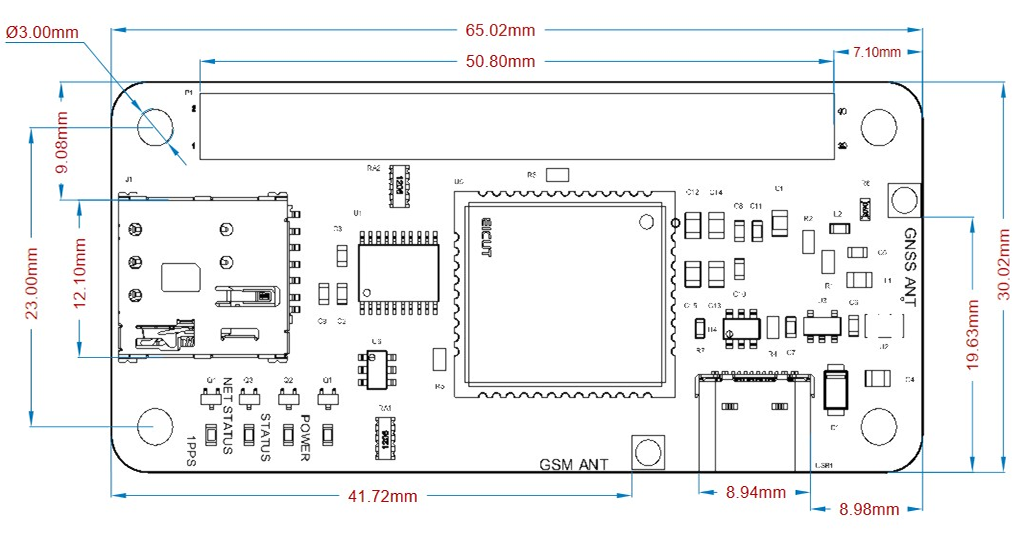
Board Dimensions #
Raspberry pi hat board dimensions:
Getting Started Preparation #
Step 1: Install Qnavigator software.
Step 2: After installation Act like a software wizard.
Step 3: Connect the Raspberry pi hat Board by USB to the computer.
(Download your driver type according to the USB model)
Step 4: select your board in the port section, set the baudrate to 115200, and click Connect.
Step 5: Click on the gear and see if the module is connected.
Step 6: By entering AT Command, you can use different parts of the module.
Make sure the power supply voltage is stable.The board powers up and turns on automatically without the need for a turn-off function.
FAQ #