LTE Evaluation Board Series B
Basic Overview #
LTE Evaluation Board Series B is designed to evaluate LTE modules and with its help you can access various features of the module. In the evaluation boards, we have tried to make all the capabilities of the module available and you can easily perform your tests with the help of this board.
Supported Module List #
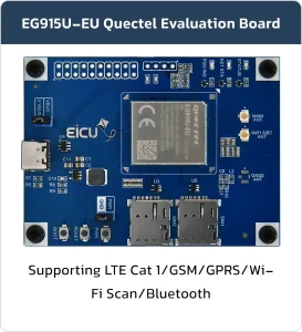
- EG915U
Evaluation Board Resources #
Function Description #
The main component and interface placement of the evaluation board is shown in the following figure:
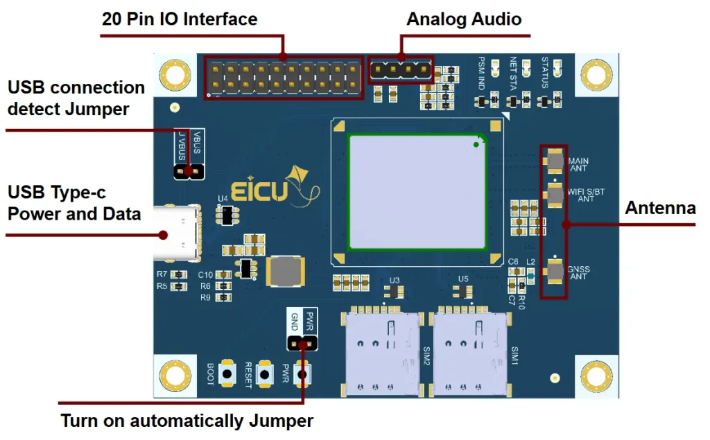
Evaluation Board Interfaces #
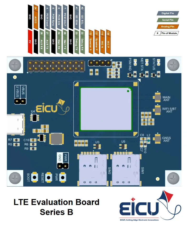
The main pin placement of the evaluation board is shown in the following figure:
| NO. | Name | Silkscreen | Comment |
|---|---|---|---|
| 1 | SIM Card Slot 1 | SIM1 | Nano-SIM |
| 2 | SIM Card Slot 2 | SIM2 | Nano-SIM |
| 3 | PWR KEY Button | PWR | Turn-on button |
| 4 | RST Button | RESET | Reset button |
| 5 | BOOT Button | BOOT | Firmware burning button |
| 6 | LTE Antenna | MAIN ANT | UFL ANTENNA connector |
| 7 | GNSS Antenna | GNSS ANT | UFL ANTENNA connector |
| 8 | DIV/WIFI/BT | WIFI_S/BT ANT | DIV / Wi-Fi / Bluetooth UFL ANTENNA connector |
- STATUS: Indicates the module’s operation status.
- NET STA: Indicates the module’s network activity status.
- PSM IND: Module Pin 1, PSM indication LED.
PIN Header #
| NO. | Name | Function | NO. | Name | Function |
|---|---|---|---|---|---|
| 1 | 5V | 5V Output | 2 | GND | Ground |
| 3 | GND | Ground | 4 | ADC0 | ADC0 testing interface |
| 5 | A RX | AUX UART Recv | 6 | GND | Ground |
| 7 | A TX | AUX UART Send | 8 | P CL | PCM clock |
| 9 | GND | Ground | 10 | P SY | PCM data frame sync |
| 11 | RX | MAIN UART Recv | 12 | P DI | PCM data input |
| 13 | TX | MAIN UART Send | 14 | P DO | PCM data output |
| 15 | GND | Ground | 16 | GND | Ground |
| 17 | D TX | Debug UART Send | 18 | SDA | I2C1 Data |
| 19 | D RX | Debug UART Recv | 20 | SCL | I2C1 Clock |
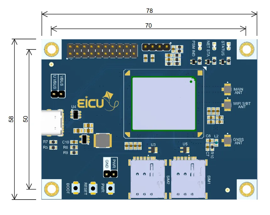
Evaluation Board Dimensions #
Getting Started Preparation #
Step 1: Install Qnavigator software.
Download QNavigator from Quectel
After downloading QNavigator, open it and continue the software tutorial by clicking Next
Step 2: After installation Act like a software wizard.
Step 3: Connect the Evaluation Board by USB to the computer.
Step 4: select your board in the port section, set the baudrate to 115200, and click Connect.
Step 5: Click on the gear and see if the module is connected.
Step 6: By entering AT Command, you can use different parts of the module.
Make sure the power supply voltage is stable. The board will power up and turn on automatically as soon as power is applied — there is no separate power-off switch required.
Downloads #
FAQ #