Description
The SIM800C Mini DB is a compact and portable board designed specifically for breadboard. The main equipped modules are the SIM800C Mini DB series wireless communication modules. The SIM800C EVB (Evaluation Board) exposes the SIM800C Quad-Band GSM/GPRS LCC module on a user-friendly breakout platform. It keeps the module’s compact LCC form factor while adding convenient connectors, power regulation, and test points so you can prototype and evaluate cellular functionality quickly without low-level PCB layout or soldering.
Features
- Compatible with BreadBoard
- On Board 2A Switching Regulator
- On Board NanoSIM(4FF) socket
- BT Antenna on board
- GNSS active antenna circuit
- Quad-band GSM/GPRS support with up to 85.6 kbps GPRS data transfer
- Abundant interfaces: UART, USB 2.0, GPIO for easy host connection and control
- Ready-to-use EVB power management, antenna connector, and level-shifted I/O
- header pins for monitoring signals and integrating peripherals
- Compact evaluation form factor that preserves the SIM800C LCC footprint for later product development
Specifications
- Module type: SIM800C in LCC package
- Network: Quad-band GSM (GPRS up to 85.6 kbps)
- Interfaces: UART, USB 2.0, multiple GPIO pins
- Expansion: Breakout headers for debugging and interfacing with external sensors or microcontrollers
- Typical use: Designed to mirror final-module connections so results transfer to production hardware
Applications
- Smart meters and metering gateways
- Security systems and alarm communication
- Remote diagnostics and telemetry
- IoT devices requiring low-bandwidth cellular connectivity
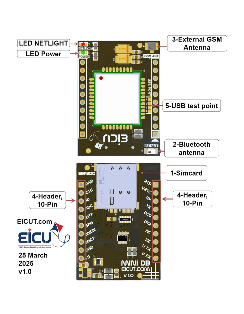
Development Board Configuration
The detailed assignment of the peripheral interfaces on the Development board is as follows:
| NO. |
Name |
Silkscreen |
Comment |
| 1 |
Sim card case |
J1 |
4FF SIM Card 12.3* 8mm |
| 2 |
External Bluetooth Antenna |
BT ANT |
Johanson Bluetooth Antenna |
| 3 |
External GSM Antenna |
GSM ANT |
UFL ANTENNA |
| 4 |
10pin |
P1-P2 |
header 2.54mm |
| 5 |
USB |
USB PORT |
USB interface which can be used for debugging and upgrading firmware; |
The Development board has 2 functional indication LEDs, as follows:
- D1: NETLIGHT
- D2: Power indication LED
Components
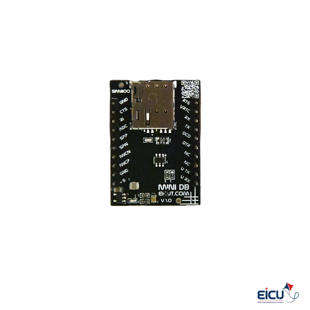
PinOut
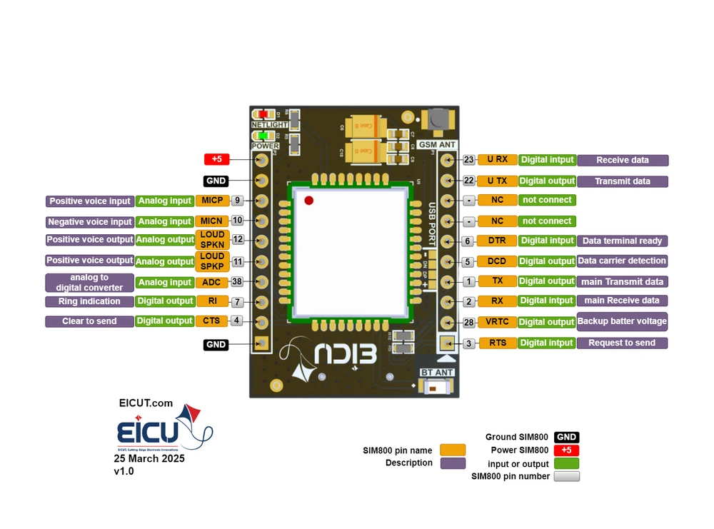
Pin Describtion
| NO. |
Name |
Silkscreen |
Comment |
| P1-1 |
Request to send |
RTS |
You can use it as an output and input. |
| P1-2 |
VRTC |
VRTC |
Power supply for RTC when VBAT is not supplied for the system. Charging for backup battery or golden capacitor when the VBAT is applied.) For the allowed voltage and current values for this pin, see the bottom of the table.) |
| P1-3 |
RXD |
RX |
Receive data |
| P1-4 |
TXD |
TX |
Transmit data |
| P1-5 |
DCD |
DCD |
Digital output |
| P1-6 |
DTR |
DTR |
Digital input |
| P1-7 |
NC |
NC |
Not connect |
| P1-8 |
NC |
NC |
Not connect |
| P1-9 |
UART2-TX |
AUXTX |
Transmit data |
| P1-10 |
UART2-RX |
AUXRX |
Receive data |
| P2-1 |
Ground |
GND |
|
| P2-2 |
CTS |
CTS |
Clear to send |
| P2-3 |
RI |
RI |
Ring indication |
| P2-4 |
ADC0 |
ADC |
General purpose analog to digital converter. Vmax=2.8V, Vmin=0V |
| P2-5 |
SPK1P |
SPP |
Channel 1 positive voice output |
| P2-6 |
SPK1N |
SPN |
Channel 1 negative voice output |
| P2-7 |
MICN |
MICN |
negative voice input |
| P2-8 |
MICP |
MICP |
Positive voice input |
| P2-9 |
Ground |
GND |
|
| P2-10 |
Power |
+5 |
Main power supply of module
Make sure that supply sufficient current in a transmitting burst typically rises to 1.6A. Vmax=4.8V, Vmin=5.5V |
VRTC pin voltage: VImax=3.3V, VImin=1.5V, VInorm=2.8V
VOmax=3V, VOmin=2V, VOnorm=2.8V IOmax=2mA Iin≈10uA
Hint: make sure the power supply voltage is stable. The board to power up and turn on automatically without the need for a turn-off function.
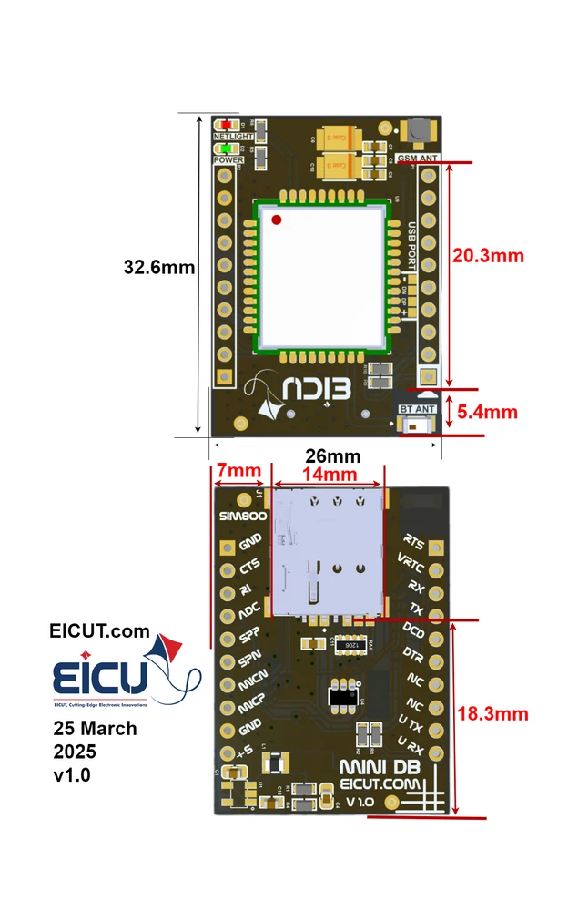
Dimentions
Benefits of the EVB for Design
Using the SIM800C EVB accelerates development and reduces risk by letting you test cellular functions immediately without designing a module-level PCB. The EVB simplifies integration, saves development time, and helps validate power, signaling, and antenna choices before committing to a final hardware design.
Downloads
 M66 mini Development Board
3 × $ 10.4
M66 mini Development Board
3 × $ 10.4 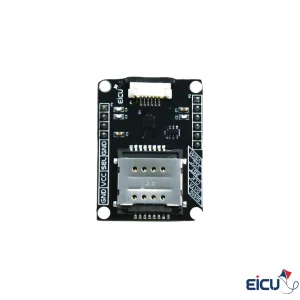 FSA2568 Dual Sim Card Analoge Switch, for 2FF USIM, FPC Cable support
1 × $ 3.9
FSA2568 Dual Sim Card Analoge Switch, for 2FF USIM, FPC Cable support
1 × $ 3.9 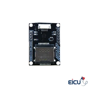 DIO1568 Dual Sim Card Analoge Switch, for 2FF USIM, FPC Cable support
1 × $ 4.5
DIO1568 Dual Sim Card Analoge Switch, for 2FF USIM, FPC Cable support
1 × $ 4.5 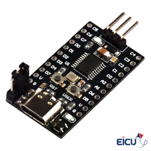 CH32V003 Mini Development Board
3 × $ 1.5
CH32V003 Mini Development Board
3 × $ 1.5 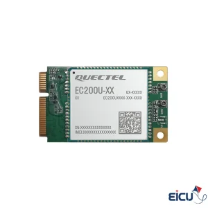 EC200U-EUAP MiniPCIe Quectel Module
1 × $ 17.2
EC200U-EUAP MiniPCIe Quectel Module
1 × $ 17.2 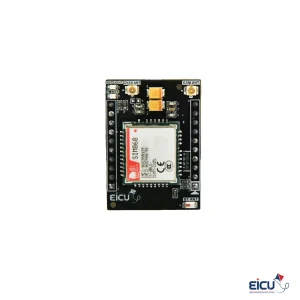 SIM868 mini Development Board for 2G/GNSS/GPS applications
1 × $ 12.9
SIM868 mini Development Board for 2G/GNSS/GPS applications
1 × $ 12.9 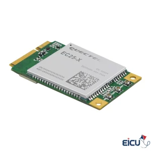 EC25-EUX Mini PCIe LTE 4G Quectel Module
1 × $ 49.0
EC25-EUX Mini PCIe LTE 4G Quectel Module
1 × $ 49.0 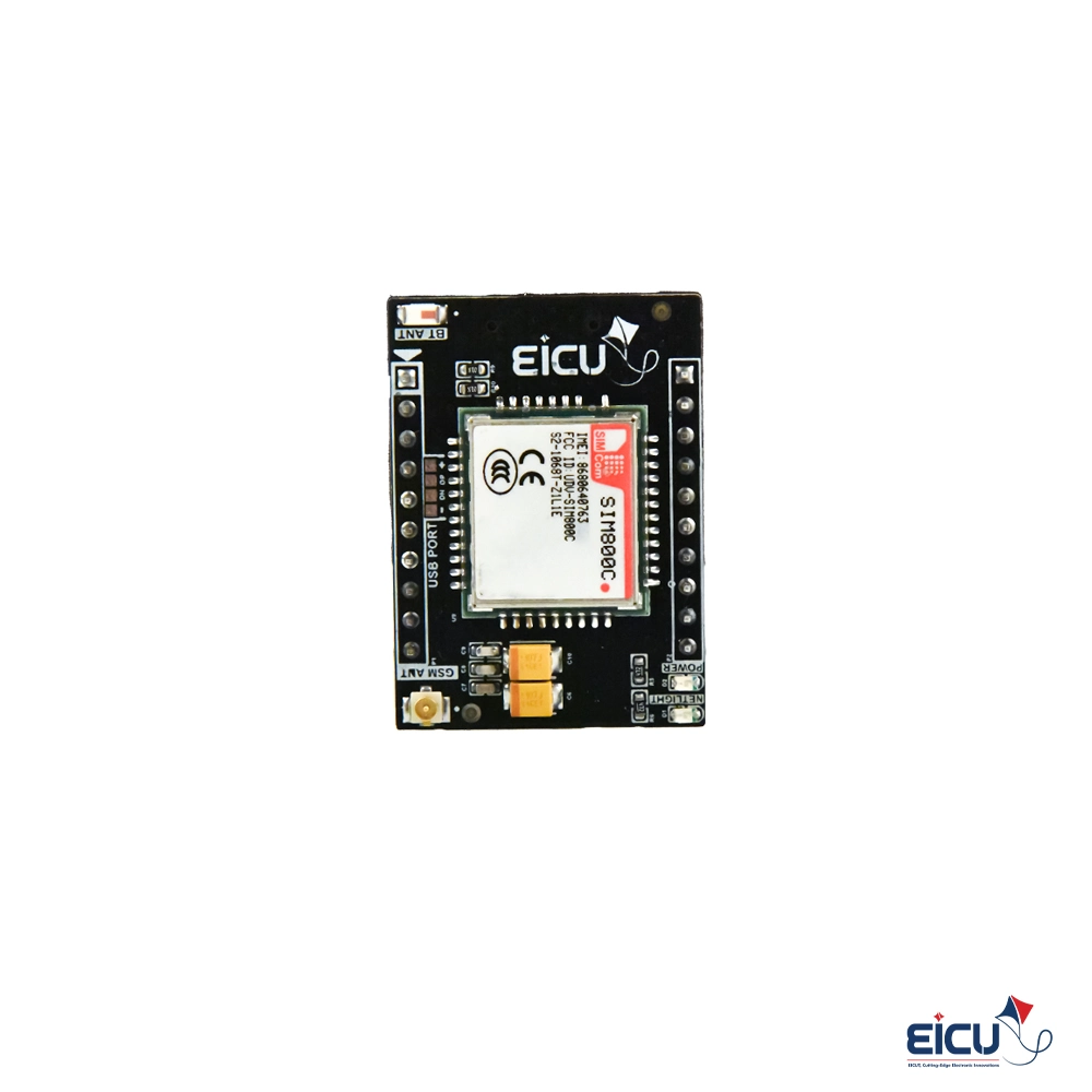
There are no reviews yet.