Description
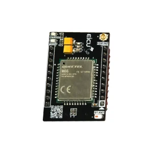
MC60 Mini Development Board (MiniDB) can greatly assist you in experimenting, testing, designing, and generally speeding up the learning and product design processes, freeing your mind from getting bogged down with peripheral technical issues. This development board is designed for the MC60 module from Quectel, allowing you to quickly set up the module and familiarize yourself with its capabilities. MC60 is a quad-band full-featured GSM/GPRS module in an LCC castellation package. It integrates GNSS for satellite navigation and delivers optimized SMS, data, and audio performance even in harsh environments.
Features
- Quad-band GSM/GPRS support
- Integrated GNSS engine for satellite navigation
- Internet protocols: TCP, UDP, PPP, FTP, HTTP, SSL
- AlwaysLocate™ and GLP (GNSS Low Power) modes for accurate positioning with very low power consumption
- Built-in LNA for improved RF sensitivity and enhanced acquisition/tracking in weak-signal areas
- AT Commands: GSM 07.07, 07.05 and Enhanced AT Commands
Specifications
- Cellular: Quad-band 2G (GSM/GPRS) based on latest 2G chipset
- GNSS: Integrated GNSS engine with EPO, QuecFastFix, EASY, AlwaysLocate™, GLP support
- Protocols: TCP, UDP, PPP, FTP, HTTP, SSL
- Power: Very-low power modes available (AlwaysLocate™, GLP)
- RF: Built-in LNA for improved sensitivity and performance
Applications
Suitable for a wide range of M2M applications, including:
- Automotive and telematics
- Wearable devices
- Asset trackers and pet trackers
Dimentions
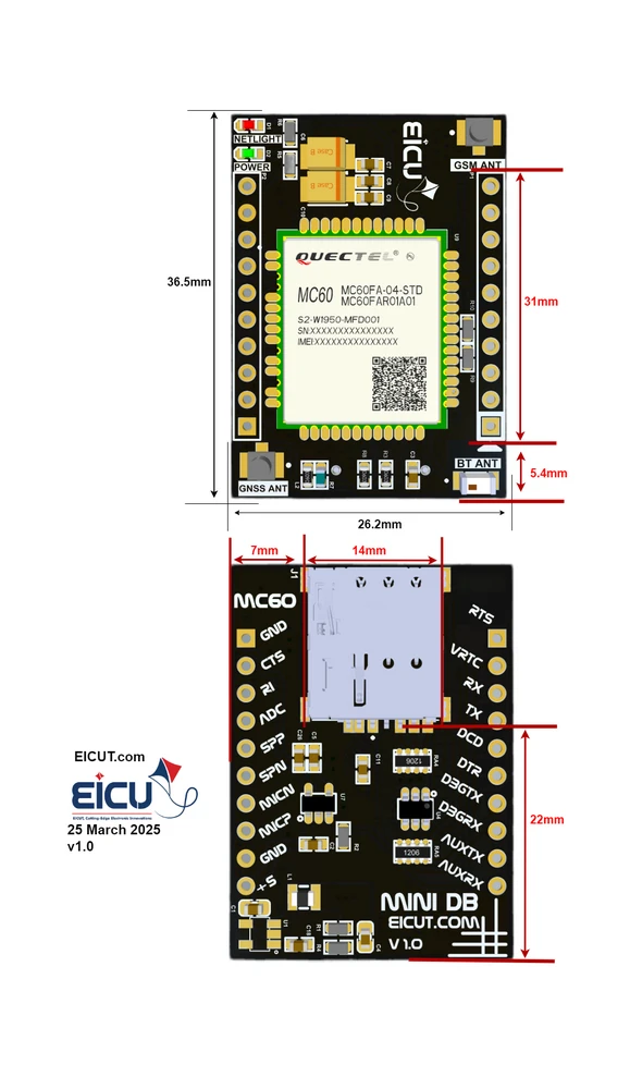
Components
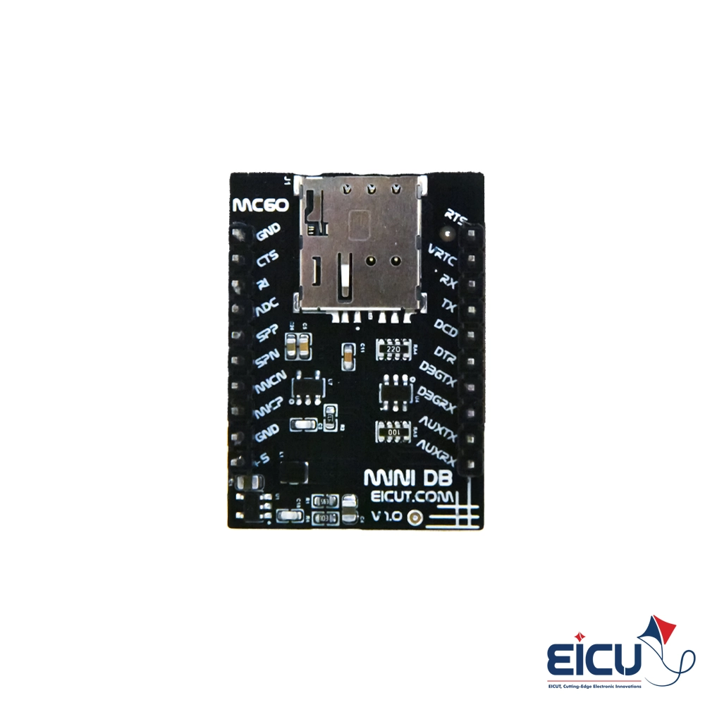
MiniDB Pinout
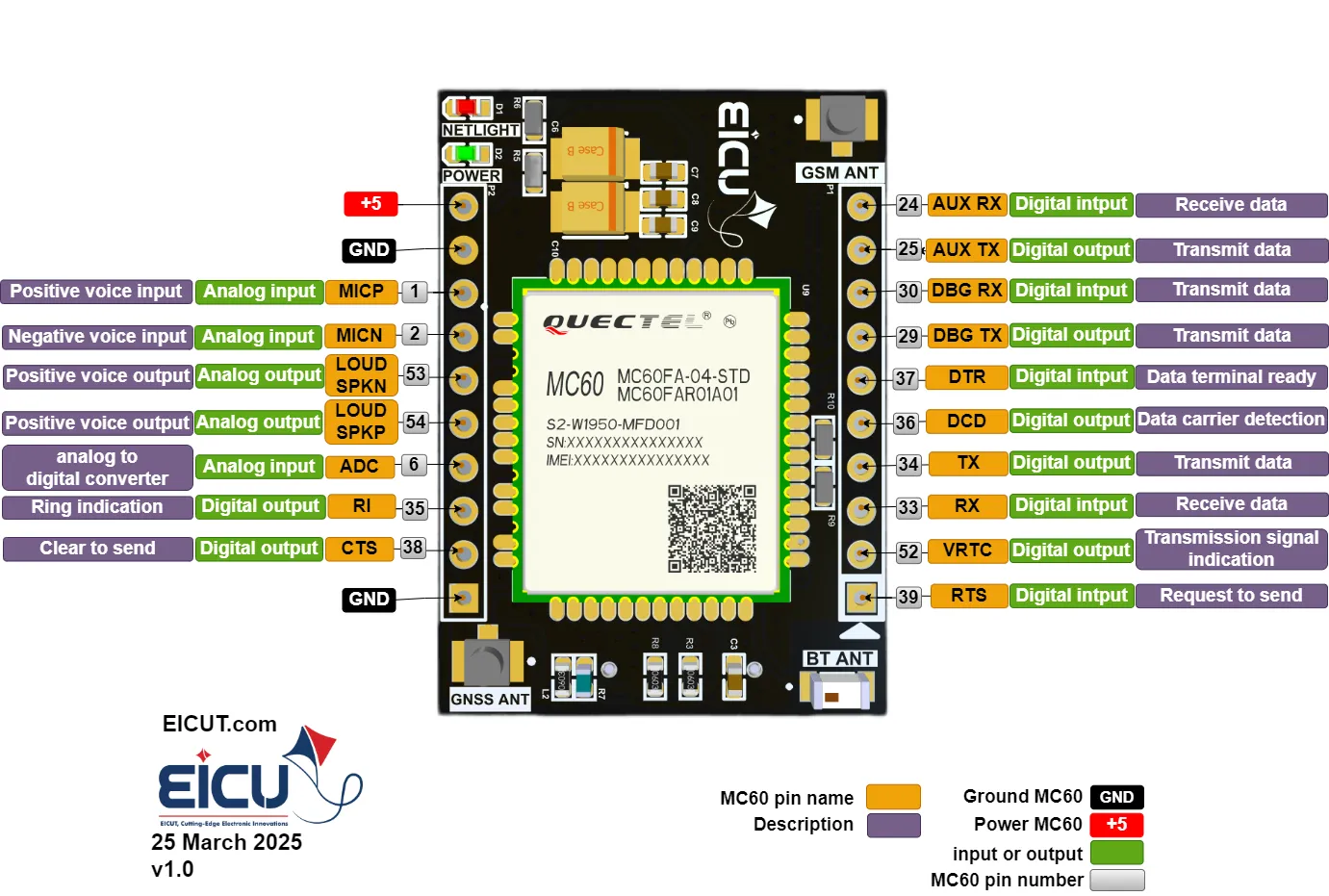
Pinout MC60 Mini DB P1-P2
| NO. |
Name |
Silkscreen |
Comment |
| P1-1 |
Request to send |
RTS |
You can use it as an output and input. |
| P1-2 |
VRTC |
VRTC |
Power supply for RTC when VBAT is not supplied for the system. Charging for backup battery or golden capacitor when the VBAT is applied.) For the allowed voltage and current values for this pin, see the bottom of the table.) |
| P1-3 |
RXD |
RX |
Receive data |
| P1-4 |
TXD |
TX |
Transmit data |
| P1-5 |
DCD |
DCD |
Digital output |
| P1-6 |
DTR |
DTR |
Digital input |
| P1-7 |
DBG-TXD |
DBGTX |
Transmit data |
| P1-8 |
DBG-RXD |
DBGRX |
Receive data |
| P1-9 |
TXD-AUX |
AUXTX |
Transmit data |
| P1-10 |
RXD-AUX |
AUXRX |
Receive data |
| P2-1 |
Ground |
GND |
|
| P2-2 |
CTS |
CTS |
Clear to send |
| P2-3 |
RI |
RI |
Ring indication |
| P2-4 |
ADC0 |
ADC |
General purpose analog to digital converter. Vmax=2.8V, Vmin=0V |
| P2-5 |
SPK1P |
SPP |
Channel 1 positive voice output |
| P2-6 |
SPK1N |
SPN |
Channel 1 negative voice output |
| P2-7 |
MICN |
MICN |
negative voice input |
| P2-8 |
MICP |
MICP |
Positive voice input |
| P2-9 |
Ground |
GND |
|
| P2-10 |
Power |
+5 |
Main power supply of module
Make sure that supply sufficient current in a transmitting burst typically rises to 1.6A. Vmax=4.8V, Vmin=5.5V |
|VRTC pin voltage: VImax=3.3V, VImin=1.5V, VInorm=2.8V
VOmax=3V, VOmin=2V, VOnorm=2.8V IOmax=2mA Iin≈10uA
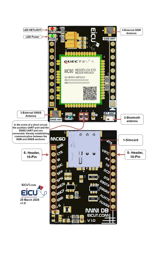
Development Board Configuration
The detailed assignment of the peripheral interfaces on the Development board is as follows:
| NO. |
Name |
Silkscreen |
Comment |
| 1 |
Sim card case |
J1 |
4FF SIM Card 12.3* 8mm |
| 2 |
External Bluetooth Antenna |
BT ANT |
Johanson Bluetooth Antenna |
| 3 |
External GSM Antenna |
GSM ANT |
UFL ANTENNA |
| 4 |
External GNSS Antenna |
GNSS ANT |
UFL ANTENNA |
| 5 |
10pin |
P1-P2 |
header 2.54mm |
The Development board has 2 functional indication LEDs, as follows:
- D1: NETLIGHT
- D2: Power indication LED.
Getting Started Preparation
- Step 1: Install Qnavigator software: https://www.quectel.com/download/qnavigator_v1-5/
- Step 2: After installation Act like a software wizard.
- Step 3: Connect the Development Board by USB to UART converter to the computer.(pin p1-3, p1-4)
- Download your driver type according to the USB-to-serial IC model
- Step 4: select your board in the port section, set the baudrate to 115200, and click Connect.
- Step 5: Click on the gear and see if the module is connected.
- Step 6: By entering AT Command, you can use different parts of the module.
- Hint: make sure the power supply voltage is stable. The board to power up and turn on automatically without the need for a turn-off function.
Downloads
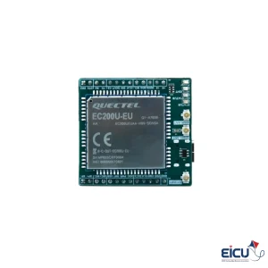 EC200U Mini Development board Supporting LTE 4G / GSM GPRS / GPS / Bluetooth / Wi-Fi Scan / Audio, Europe band compatible
1 × $ 19.9
EC200U Mini Development board Supporting LTE 4G / GSM GPRS / GPS / Bluetooth / Wi-Fi Scan / Audio, Europe band compatible
1 × $ 19.9 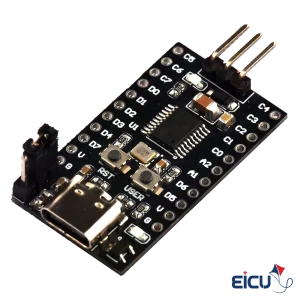 CH32V003 Mini Development Board
1 × $ 1.5
CH32V003 Mini Development Board
1 × $ 1.5 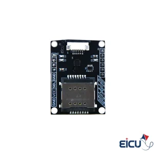 DIO1568 Dual Sim Card Analoge Switch, for 2FF USIM, FPC Cable support
1 × $ 4.5
DIO1568 Dual Sim Card Analoge Switch, for 2FF USIM, FPC Cable support
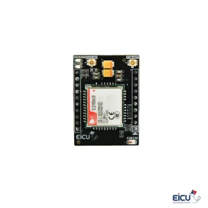
1 × $ 4.5  SIM800C mini Development Board for 2G applications
1 × $ 10.9
SIM800C mini Development Board for 2G applications
1 × $ 10.9 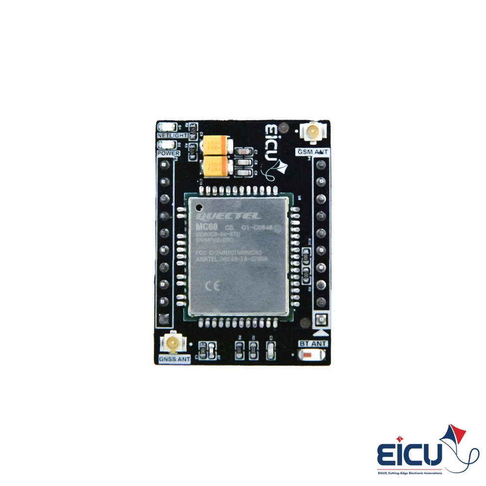
There are no reviews yet.