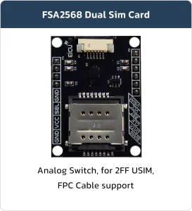

2FF Dual Simcard switch
Basic Overview #
The Switch Simard Is a compact and integrated development board designed specifically to be used on products and save a lot of time handling GSM & GNSS power circuits and etc.
Feature List #
- Dual SIM, Single Standby
- Easy Switching
- Compatible with Breadboard
- Surge Protection 5A
- On Board MiniSIM(2FF) socket
Development Board Resources #
Function Description #
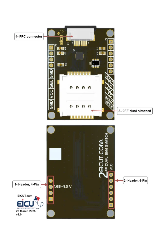
The main component and interface placement of the development board is shown in the following figure:
Development Board Configuration #
The detailed assignment of the peripheral interfaces on the Development board is as follows:
| NO. | Name | Silkscreen | Comment |
|---|---|---|---|
| 1 | 4pin | P3 | Header 2.54 mm |
| 2 | 6pin | P2 | Header 2.54 mm |
| 3 | Dual Sim card case | – | 2FF SIM Card |
| 4 | FPC Connector | P1 | FPC 6pin |
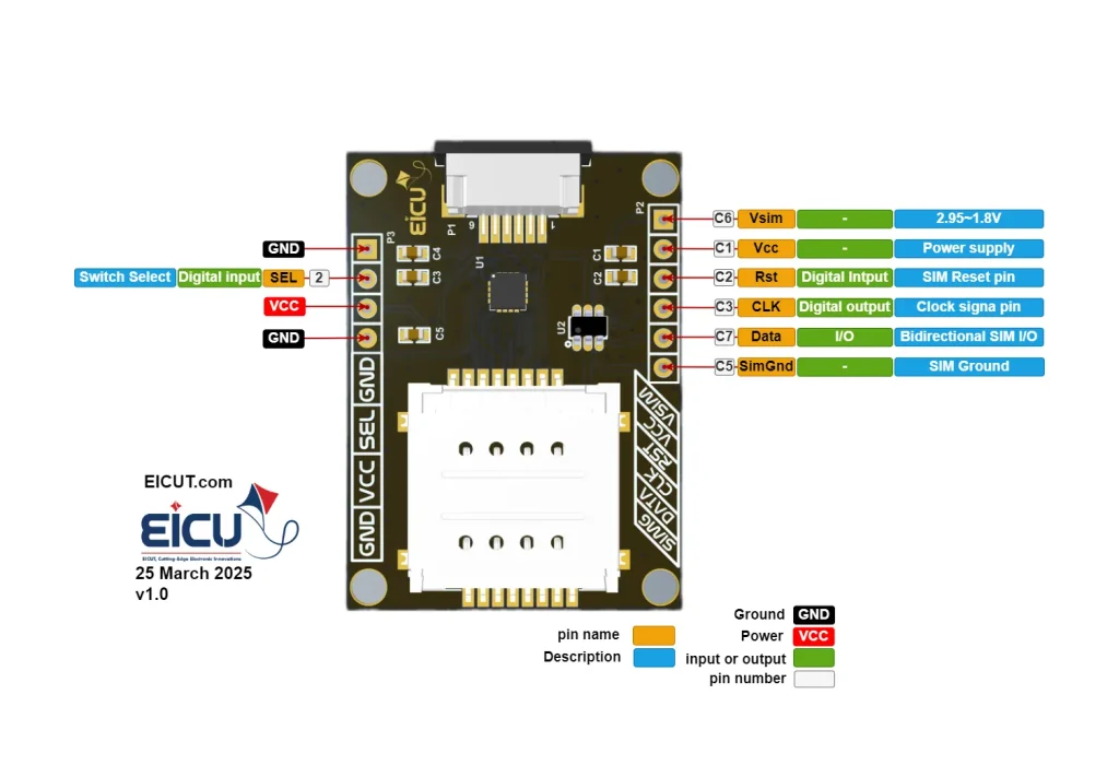
Development Board Interfaces #
| NO. | Name | Silkscreen | Comment |
|---|---|---|---|
| P3‑1 | Ground | GND | – |
| P3‑2 | Select | Sel | 0 – Power |
| P3‑3 | Power | VCC | 1.65–4.3 V |
| P3‑4 | Ground | GND | – |
| P2‑1 | VSIM | VSIM | These pins are similar to the pins of the FPC connector. You can use them if you do not use the FPC connector. |
| P2‑2 | VCC | VCC | – |
| P2‑3 | RST | RST | – |
| P2‑4 | CLK | CLK | – |
| P2‑5 | DATA | DATA | – |
| P2‑6 | Simcard-GND | SIMG | – |
For switching between two SIM cards, you can connect the Select pin (pin header P3) to ground or VCC manually with a jumper, or you can control this pin using a microcontroller to set it high or low.
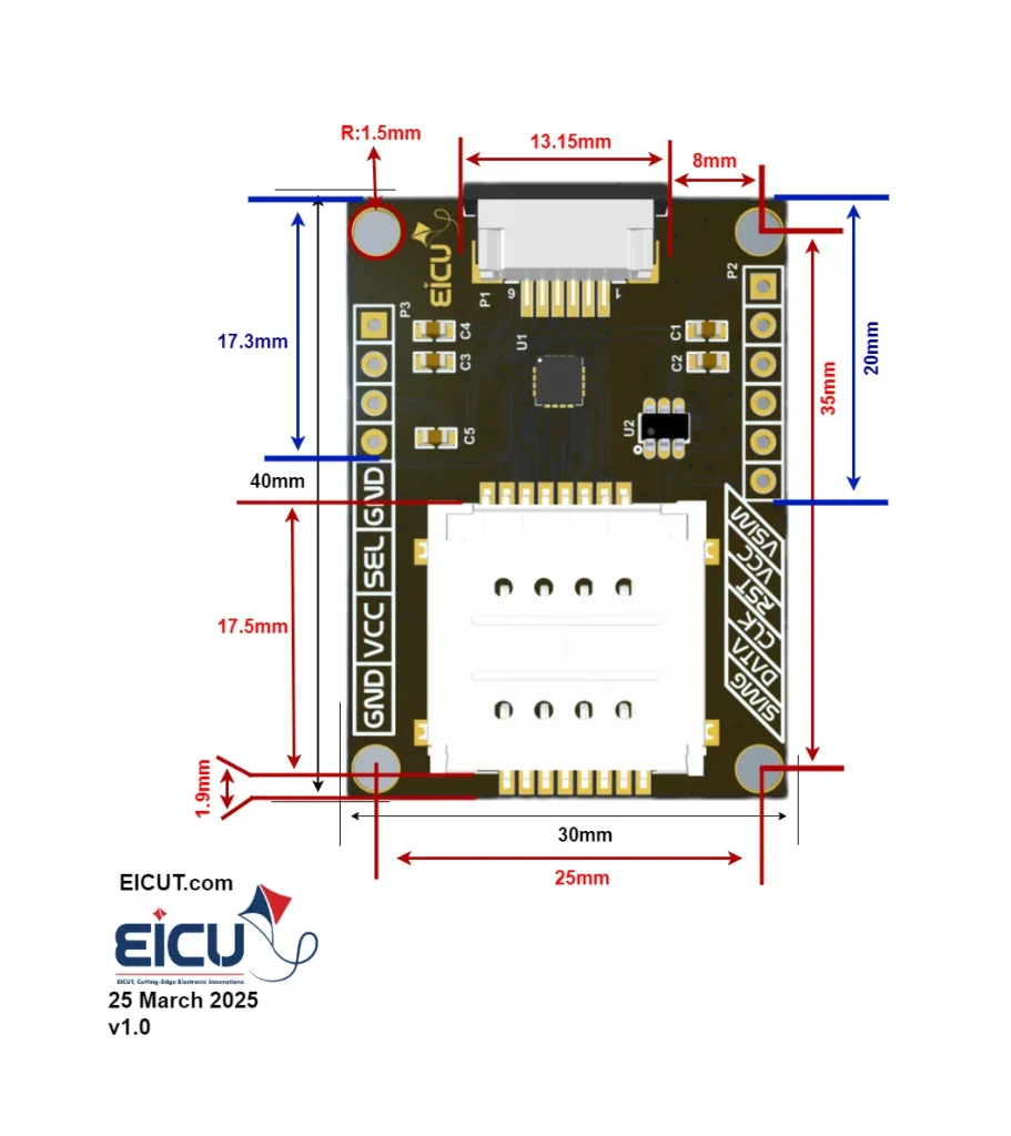
Development Board Dimensions #
The main pin placement of the Development board is shown in the following figure:
Getting Started Preparation #
Step 1: Connect the board power
Step 2: Place the SIM cards in the SIM card case
Step 3: Switch between SIM cards by High and Low the select pin
Step 4: Connect the board to your microcontroller with the FPC connector or the header pin(P2)
Resource Download #
FAQ #