Introduction to Mini-PCI Hat Board
Basic Overview #
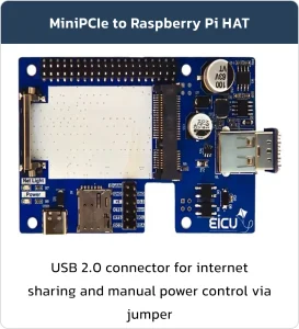
The Mini-PCI HAT is a versatile interface board designed for connecting Mini-PCI modules and sharing data over USB. While it follows the Raspberry Pi pinout for seamless integration, it can also be used as a standalone board or with other similar platforms. In addition, processor interface pins allow direct control of the Mini-PCI module.
Feature List #
- SIM card socket
- Powerful 3A regulator for reliable Mini-PCI module power supply
- Status LEDs for module activity indication
- USB Type-C connector for power input
- USB 2.0 Type-A socket for data sharing
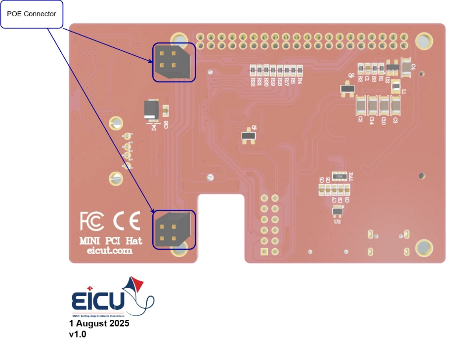
Power over Ethernet (PoE) Class 4 circuit compliant with IEEE 802.3af/at standard, providing up to 25.5 W of power to the board through a single Ethernet cable
Board Resources #
Function Description #
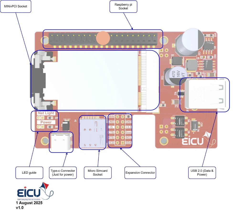
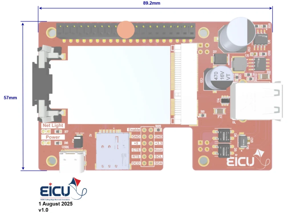
The main component and interface placement of the evaluation board is shown in the following figure:
- If you are using it in standalone mode, connect the Enable jumper so that the module is powered.
- If you are using it as a Raspberry Pi HAT, set the Enable pin on the Raspberry Pi interface to 1 to turn on the module.
Board Interfaces #
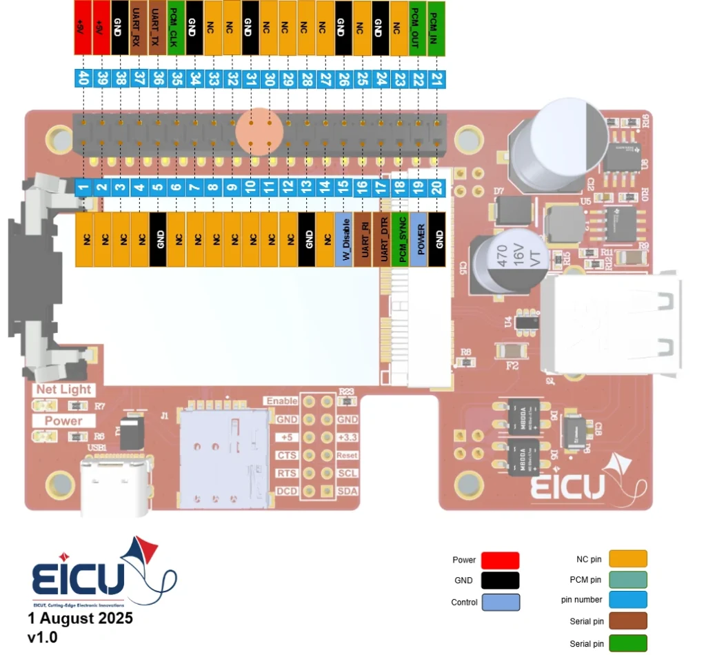
The main pin placement of the evaluation board is shown in the following figure:
| NO. | Name | Comment |
|---|---|---|
| 1 | Raspberry pi Socket | |
| 2 | Mini-PCI Socket | |
| 3 | LED Guide | |
| 4 | USB Type-C | Only for Power |
| 5 | Micro Simcard Socket | |
| 6 | Expansion Connector | |
| 7 | USB 2.0 | |
| 8 | POE Connector |
Evaluation Board Dimensions #
Getting Started Preparation #
Software Requirements #
Run the following commands to install the necessary software:
sudo apt update
sudo apt upgrade
sudo apt install libqmi-utils
Verifying Hardware Connection #
With your module connected to the development board, run:
|
1 |
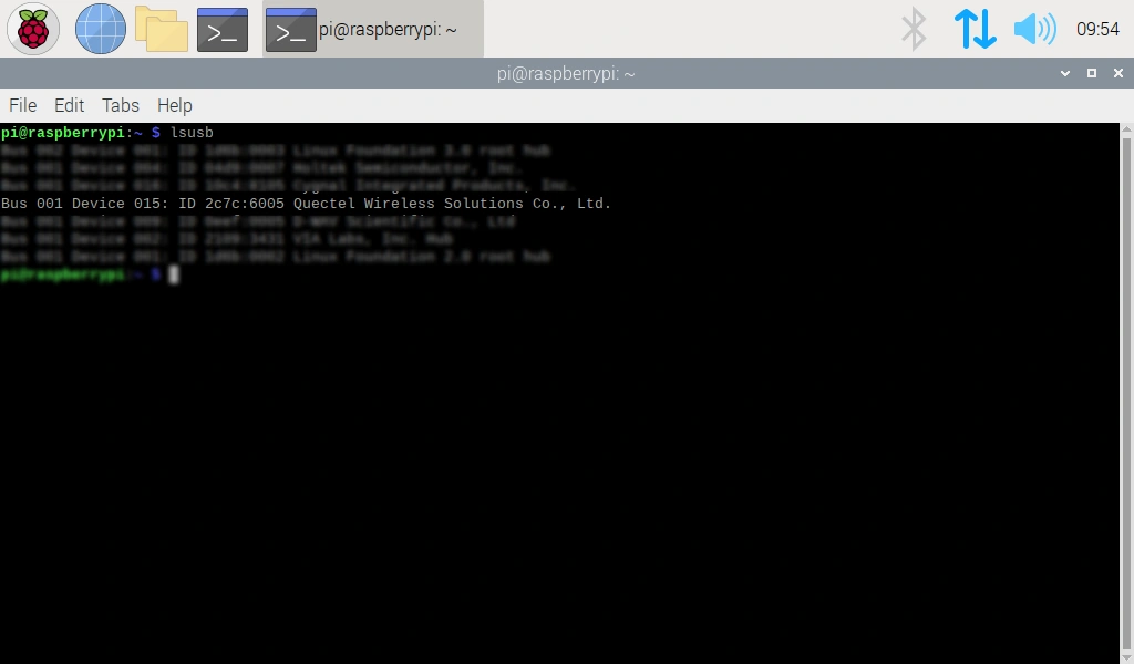
lsusb |
If the module is detected correctly, you should see its vendor and product ID listed in the output,
similar to the example provided in the photo.
Next, check for the network interface:
|
1 |
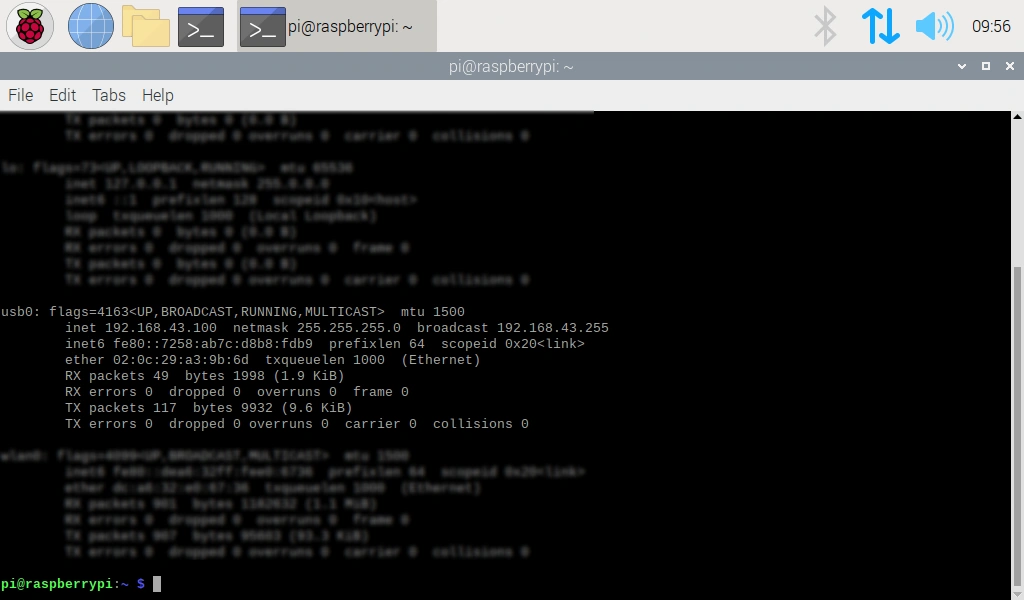
ifconfig -a |
You should see a usb0 network interface appear in the list.
Module Configuration #
Some modules require additional configuration. To set this up, first install and use a serial communication tool:
|
1 2 |
sudo apt install minicom -y minicom -D /dev/ttyUSB0 -b 115200 |
Note: ttyUSB0 is the serial port of my 4G module. If you are unsure which port your module is using, you can identify it with:
|
1 |
lsusb -v -d 2c7c:6005 | grep “interface” |
The ID used with lsusb -v -d (e.g., 2c7c:6005) comes from the vendor and product ID you noted
earlier when you ran lsusb.
Once connected to the correct port via Minicom, you can send AT commands to the module. To
verify that the device is connected and responding correctly, send AT. The module should respond
with OK.
If the connection is successful, proceed with the following configuration commands:
|
1 2 3 4 |
AT+QCFG="usbnet",1 AT+AUTOAPN=0 AT+QICSGP=1,1,"Access Point Name","","",0 AT+QNETDEVCTL=1,1,1 |
Important: You must replace <Access Point Name> with the actual APN provided by your mobile carrier. If you do not know your APN, you can obtain it from your SIM card provider. APNs vary
between different network operators (such as Airtel, Vodafone, Idea, etc.). Also, please keep in mind
that this step is optional; skip it if your module does not support AUTOAPN
Using UART of Raspberry Pi to communicate with module #
If you want to communicate with the module through the Raspberry Pi’s on-board UART follow
these steps.
Enable Raspberry Pi UART interface
Run:
|
1 |
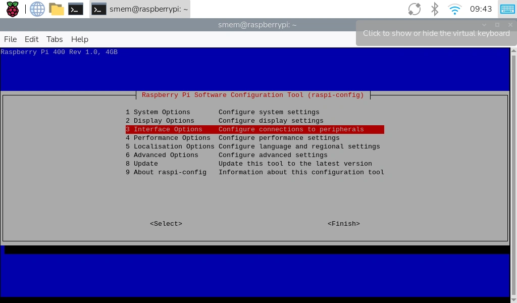
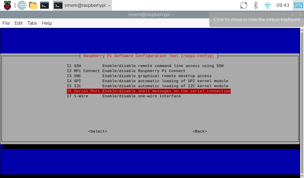
sudo raspi-config |
Navigate to:
Interface Options → Serial Port
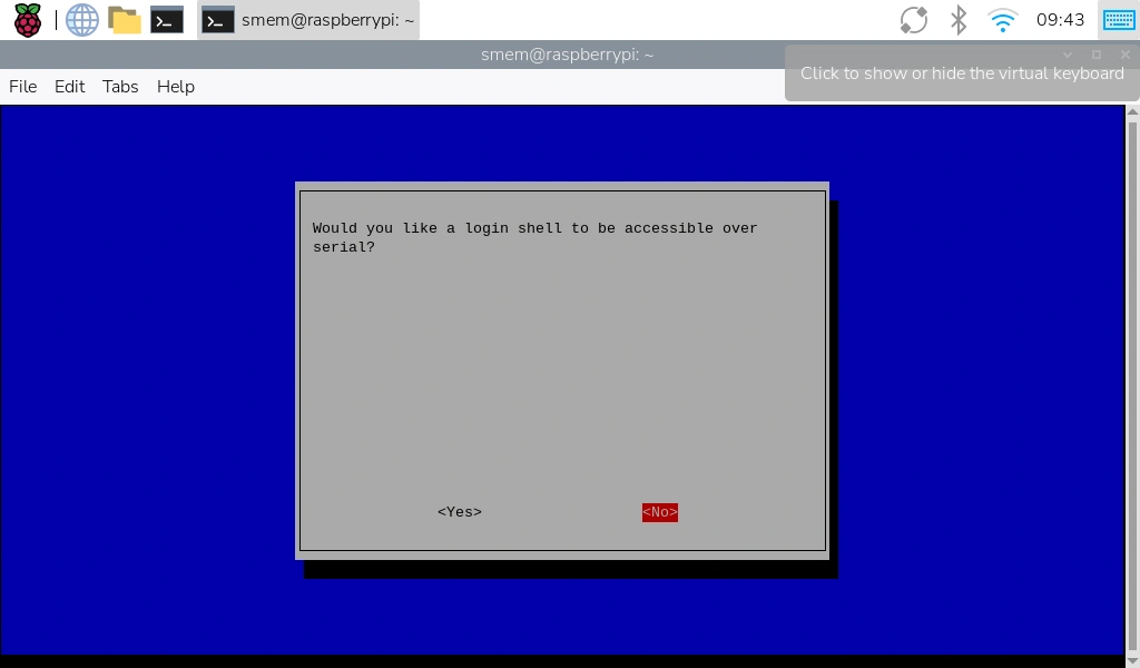
When prompted:
1. “Login shell over serial?” → No (this prevents the Pi’s terminal from occupying the UART)
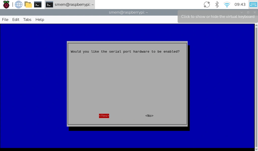
2. “Enable hardware serial port?” → Yes
Exit and reboot your system when prompted.
After the reboot, verify the serial interface:
|
1 |
ls -l /dev/serial* |
You should see something like /dev/serial0 (typically linked to /dev/ttyAMA0 or /dev/ttyS0
depending on your Pi model).
The last step is opening a terminal session to the modem:
|
1 |
sudo minicom -D /dev/serial0 -b 115200 |
Type AT and press Enter → you should receive OK. That confirms the UART path is working
FAQ #