Introduction to DIO1568 Analog Switch
Basic Overview #
The DIO1568 Evaluation Board (EVB) provides an easy and efficient way to test and develop prototypes using the DIO1568, a low-power quad SPDT analog switch specifically designed for dual-SIM card switching applications. Operating from a wide supply voltage range of 1.65 V to 5.5 V, this device features extremely low on-resistance of just 0.85 Ω across the SIM signal paths and ensures reliable break-before-make switching performance thanks to advanced sub-micron CMOS technology. It also draws minimal quiescent current even when the control logic voltage is lower than VCC, allowing direct connection to baseband processor GPIO pins in smartphones and other portable devices. The DIO1568 is offered in two small-footprint QFN packages: 1.8 × 2.6 mm (16-pin) and 3 × 3 mm (16-pin).
Feature List #
- Switch type: Quad SPDT (4×)
- Supply voltage: 1.65 V to 5.5 V
- Low on-resistance: 0.85 Ω (SIM path); 2.7 Ω (other paths)
- Capacitance: 20 pF CON at DAT/CLK/RST path
- Low quiescent power consumption (suitable for battery-powered devices)
- Package options: 16‑lead QFN 1.8×2.6 mm and 16‑lead QFN 3×3 mm
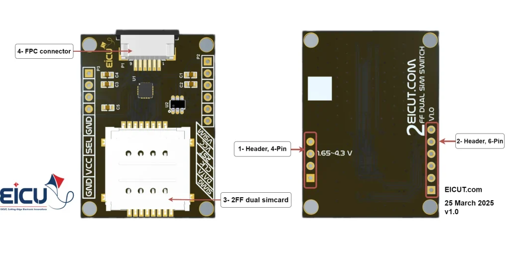
Board Resources #
Function Description #
The detailed assignment of the peripheral interfaces on the Development board is as follows:
| NO. | Name | Silkscreen | Comment |
|---|---|---|---|
| 1 | 4pin header | P3 | header 2.54mm |
| 2 | 6pin header | P2 | header 2.54mm |
| 3 | Dual Sim card case | – | 2FF SIM Card |
| 4 | FPC Connector | P1 | FPC 6pin |
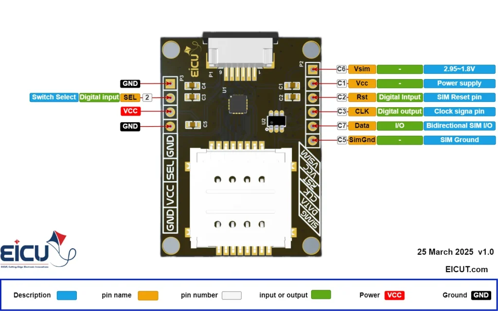
Board Interfaces #
| NO. | Name | Silkscreen | Comment |
|---|---|---|---|
| P3-1 | Ground | GND | – |
| P3-2 | Select | Sel | 0 – Power |
| P3-3 | Power | VCC | 1.65~4.3V |
| P3-4 | Ground | GND | – |
| P2-1 | VSIM | VSIM | These pins are similar to the pins of the FPC connector. You can use them if you do not use the FPC connector. |
| P2-2 | VCC | VCC | |
| P2-3 | RST | RST | |
| P2-4 | CLK | CLK | |
| P2-5 | DATA | DATA | |
| P2-6 | Simcard-GND | SIMG |
For switching between two SIM cards, you can connect the Select pin (pin header P3) to ground or VCC manually with a jumper, or you can control this pin using a microcontroller to set it high or low.
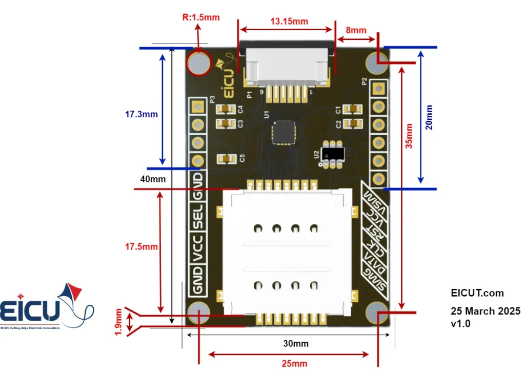
Board Dimensions #
Getting Started Preparation #
Step 1: Connect the board power
Step 2: Place the SIM cards in the SIM card case
Step 3: Switch between SIM cards by High and Low the select pin
Step 4: Connect the board to your microcontroller with the FPC connector or the header pin(P2)
Resources Downloads #
FAQ #