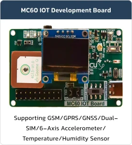
MC60-IOT Board
Basic Overview #
The MC60-IoT Board is a powerful and versatile development platform tailored for Internet of Things (IoT) applications. It is specifically designed to enable embedded developers to prototype, test, and deploy their projects without any hardware limitations.
Whether you’re building a tracking device, an environmental monitor, or a connected smart solution, this board provides all the essential tools for rapid development and smooth transition to large-scale production.
Feature List #
- Developer-friendly design for fast prototyping and testing
- Comprehensive hardware features including GNSS, Bluetooth, sensors, power management, and audio interfaces
- Suitable for both development and industrial-scale manufacturing
- Flexible configuration options for UART routing, power control, and antenna selection
- Dual Status LEDs for system and operation indication
- Embedded Temperature & Humidity Sensor (SHT40) with internal heater for enhanced accuracy
- High-Precision, Low-Power 6-Axis Accelerometer (ICM-42670-P)
- FL Connector for external GNSS antenna
- Optimized Li-Po Charging Circuit designed for 200mAh battery with charging status LED
- Manual Battery Power Switch for safe disconnection
- Onboard Bluetooth Antenna
- USB Type-C Connector with support for programming the MC60 module
- UART Mode Selector Switch for toggling between programming and custom user mode
- Configurable Jumpers to route GNSS UART output to the module’s UART
- Li-Po Battery Socket for easy battery connection
- 16MB Flash Memory for data storage and firmware
- Standard Microphone and Speaker Connectors
- Dual-SIM Socket – second SIM slot optionally usable for SD card
- Support for Internal GNSS Antenna or External Active GNSS via U.FL Connector
With its built-in sensors, dual SIM support, flash memory, and a wide range of connectivity options, the MC60-IoT Board gives embedded engineers everything they need to take their ideas from concept to final product — simple, fast, and professional.
Product Parameters #
| Product Parameters | |
|---|---|
| USB Port | Operating Level 5V |
| Interface Type-C | |
| Maximum current 200mA self-recovery fuse | |
| Transmission Distance About 5m | |
| Pin header | Operating Level 4.5~5V |
| Maximum current 500 mA | |
| Usage Environment | Temperature Range -15°C ~ 70°C |
| Humidity Range 5% ~ 95%RH | |
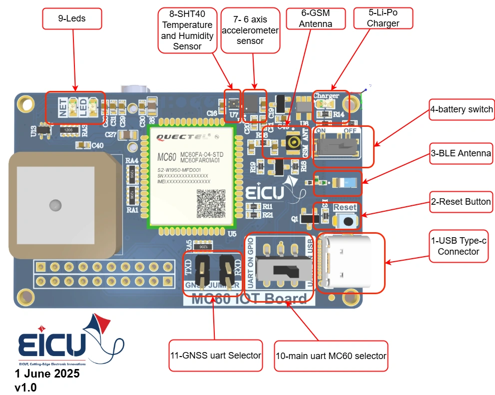
Board Resources #
Function Description #
| Number | Component / Symbol | Function / Description |
|---|---|---|
| 1 | USB Type-C Connector | USB Type-C port for power supply and data communication (programming/debugging) |
| 2 | Reset Button | Hardware reset button for the module (MC60) |
| 3 | BLE Antenna | Bluetooth Low Energy antenna for BLE communication |
| 4 | Battery Switch | ON/OFF switch for Li-Po battery power path |
| 5 | Li-Po Charger | Built-in Li-Po battery charger circuit |
| 6 | GSM Antenna | GSM/GPRS antenna connection point |
| 7 | 6-axis Accelerometer Sensor | 6-axis motion sensor (accelerometer + gyroscope) |
| 8 | SHT40 Temperature & Humidity Sensor | High-accuracy temperature and humidity sensor |
| 9 | LEDs (NET LED & others) | Status indicator LEDs (NET for network status, etc.) |
| 10 | Main UART MC60 Selector | Jumper/switch to select main UART path for MC60 module |
| 11 | GNSS UART Selector | Jumper/switch to select GNSS UART path |
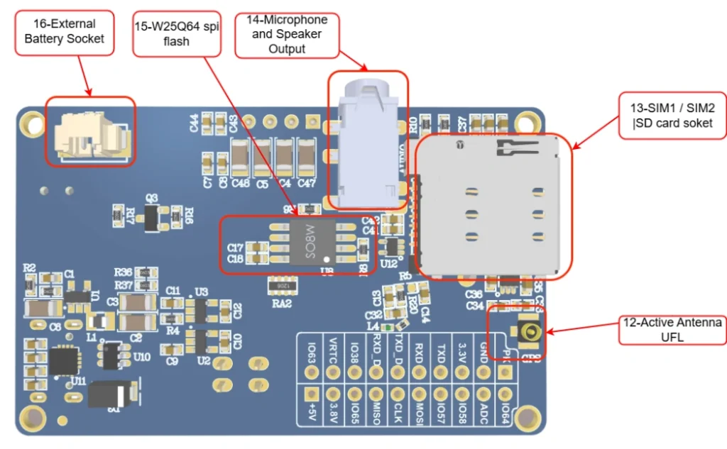
| 12 | Active Antenna U.FL | U.FL connector for external active GNSS antenna |
| 13 | SIM1 / SIM2 / SD card socket | Dual SIM card slot (SIM1/SIM2) + SD card socket |
| 14 | Microphone and Speaker Output | Analog audio input (microphone) and output (speaker) |
| 15 | W25Q64 SPI Flash | External 8MB SPI flash memory (64 Mbit) |
| 16 | External Battery Socket | Connector/socket for external Li-Po battery |
Board Interfaces #
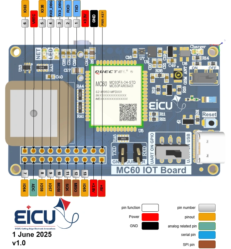
| Symbol | Description |
|---|---|
| 5V | 5V power supply |
| PWR-KEY | PWR-KEY module base |
| +3.8V | Output voltage 3.8 V |
| GND | Ground |
| IO56 | Input and output pin 56 of the module |
| +3.3V | Output voltage 3.3 V |
| MISO | SPI master-in slave out |
| TXD | TXD DBG (without level shifter) |
| SCK | SPI clock |
| RXD | RXD DBG (without level shifter) |
| MOSI | SPI master-out slave in |
| TXD_D | The TXD pin of the module is accessible using a slide switch (without level shifter) |
| IO57 | Input and output pin 57 of the module |
| RXD_D | The RXD pin of the module is accessible using a slide switch (without level shifter) |
| IO58 | Input and output pin 58 of the module |
| IO38 | Input and output pin 36 of the module |
| ADC | ADC pin from module |
| VRTC | VRTC pin from module |
| IO64 | Input and output pin 64 of the module |
| IO36 | Input and output pin 36 of the module |
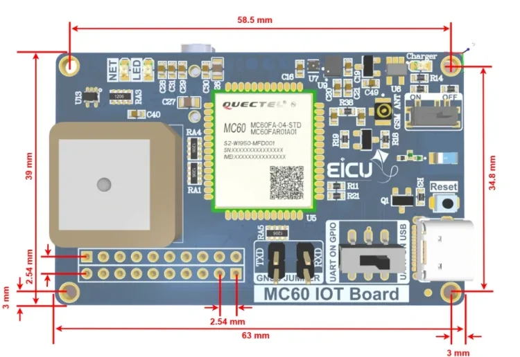
Board Dimensions #
Quick Test #
Quick module setup and testing
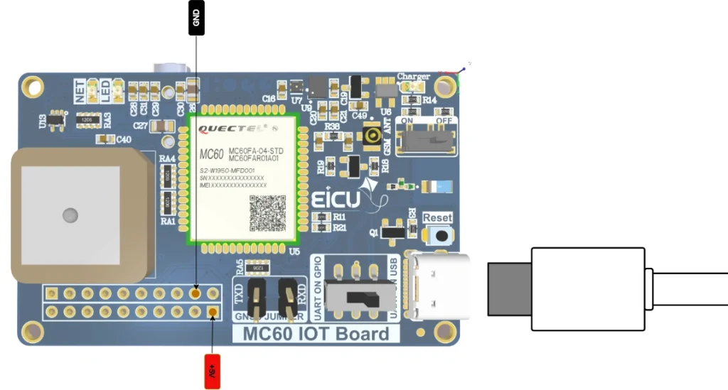
Hardware Connection #
By connecting 5V or connecting the USB port, you can provide the required power to the board.
After connecting the power, the NET LED will start blinking after a few seconds.
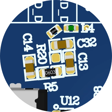
To select which antenna to use (ceramic or active), you can configure it by soldering either R5 or R22.
• To use an active antenna, solder R22 as shown in the diagram.
• To use the ceramic antenna (default option), solder R5 instead.

FAQ #