EC200 mini DB
Basic Overview #
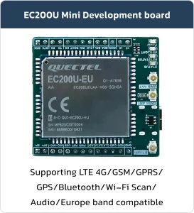
The EC200 mini DB (Development board) is a versatile and feature-rich development platform, making it an excellent choice for working with the EC200 module. It is designed to facilitate IoT prototyping and supports various applications, including smart home solutions, thanks to its integrated connectivity options and modular design.
Feature List #
-
- Main UART Port: Used for AT commands and data transmission.
- Debug UART Port: Used for debugging and logging only, not a general-purpose UART
- AT Commands: Compliant with 3GPP TS 27.007 and 27.005, including new GM AT commands
- Network Indicator: NET_STATUS pin indicates network status
- GNSS interface (ANT_GNSS)
- Normal operating temperature: 35°C to +75°C
- USB 2.0 high-speed interface
- USIM/SIM card interface (supports 3V and 1.8V)
- ADC interface
Development Board Resources #
Function Description #
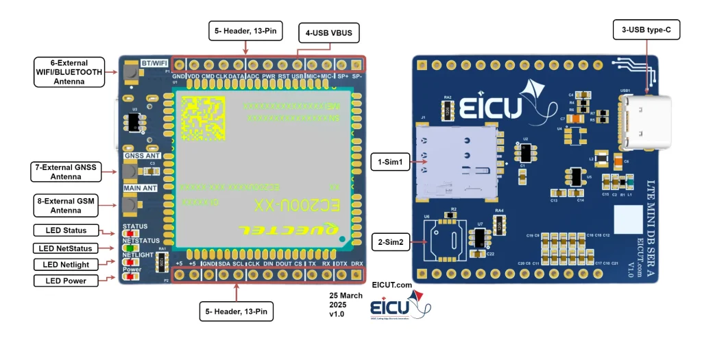
The detailed assignment of the peripheral interfaces on the Development board is as follows:
| NO. | Name | Silkscreen | Comment |
|---|---|---|---|
| 1 | Simcard1 case | SIM1 | 4FF SIM Card 12.3 × 8 mm |
| 2 | Simcard2 case | SIM2 | MFF2 SIM Card |
| 3 | USB TYPE-C | USB1 | USB interface for debugging and firmware upgrades |
| 4 | USB VBUS | U VBUS/VBUS | USB insertion detection |
| 5 | Pin header 13 pin | – | Header 2.54 mm |
| 6 | External WIFI/Bluetooth Antenna | BT/WIFI | UFL ANTENNA |
| 7 | External GNSS Antenna | GNSS ANT | UFL ANTENNA |
| 8 | External GSM Antenna | MAIN ANT | UFL ANTENNA |
The EC200 mini Development board LEDs:
- D1: Indicate module’s operating status LED
- D2: Indicate the module’s network registration mode LED
- D3: Indicate the module’s network activity status indication LED
- D4: Indicate Power LED
Board Interfaces #
The main pin placement of the Development board is shown in the following figure:

- Pin Header
| NO. | Name | Silkscreen | Comment | Interface |
|---|---|---|---|---|
| P1‑1 | LOUDSPK_N | SP- | Microphone analog input (-) | Analog |
| P1‑2 | LOUDSPK_P | SP+ | Loudspeaker differential output (+) | Audio |
| P1‑3 | MIC_N | MIC- | Microphone analog input (-) | Analog |
| P1‑4 | MIC_P | MIC+ | Microphone analog input (+) | Audio |
| P1‑5 | USB_BOOT | USB | The USB_BOOT cannot be pulled up before startup and can be used as KEYIN0 after startup. | — |
| P1‑6 | RESET_N | RST | Reset the module | — |
| P1‑7 | PWRKEY | PWR | Turn on/off the module | — |
| P1‑8 | ADC0 | ADC | General-purpose ADC interface | — |
| P1‑9 | SDIO1_DATA | DATA | SDIO data bit 0 | — |
| P1‑10 | SDIO1_CLK | CLK | SDIO clock | SD Card |
| P1‑11 | SDIO1_CMD | CMD | SDIO command | — |
| P1‑12 | SDIO1_VDD | VDD | SDIO power supply | — |
| P1‑13 | GND | Ground | — | — |
| P2‑1 | DEBUG_RXD | DBG RX | DEBUG serial port receiving | Debug |
| P2‑2 | DEBUG TXD | DBG TX | DEBUG serial port sending | UART |
| P2‑3 | MAIN TX | TX | The module sends data. Used for AT commands. | Main |
| P2‑4 | MAIN RX | RX | The module receives data. Used for AT commands. | UART |
| P2‑5 | SPI_CS | CS | SPI chip select | — |
| P2‑6 | SPI_MOSI | DOUT | SPI master mode output | SPI |
| P2‑7 | SPI_MISO | DIN | SPI master mode input | — |
| P2‑8 | SPI_CLK | CLK | SPI clock | — |
| P2‑9 | I2C_SCL | SCL | I2C serial clock | I2C |
| P2‑10 | I2C_SDA | SDA | I2C serial data | — |
| P2‑11 | GND | Ground | — | — |
| P2‑12 | Power +5 | +5 | — | — |
| P2‑13 | Power +5 | +5 | — | — |
Board Dimensions #

Make sure the power supply voltage is stable.
Getting Started Preparation #
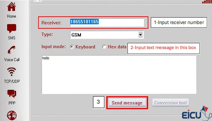
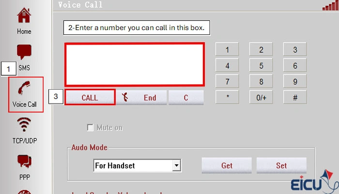
The EC200 is a GPS and GNSS module that allows you to determine your geographical position with high accuracy as well as enabling contact and SMS functionalities. QNavigator is a user-friendly software designed for managing and analyzing GPS data or send SMS and call and…. In this tutorial, we will cover the steps to set up and use the EC200 with QNavigator.
- Install the EC200 Driver:
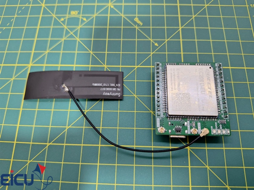
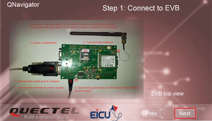
Download and install the appropriate driver for the EC200 module on your computer. - Connect the Antenna:
Take the antenna included in the package and connect it to the Main Ant port on the EC200 module. - Connect the Module to Your Computer:
Use a USB Type-C cable to connect the EC200 module to your computer. - Verify Recognition:
If the driver is installed correctly, the module should be recognized by your system as shown in the image below.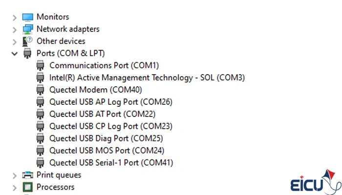
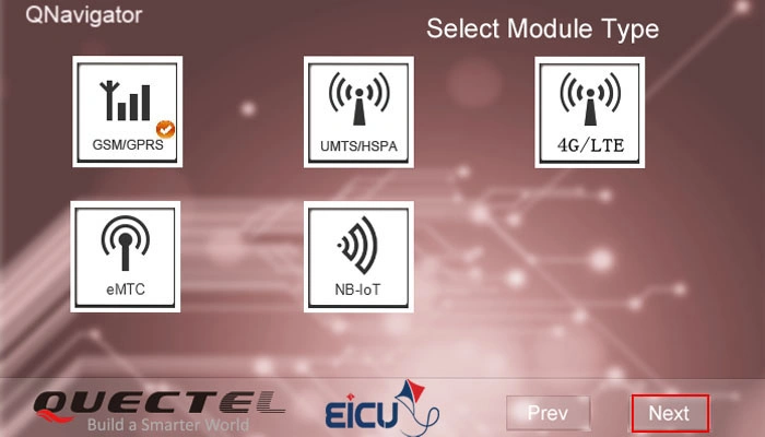
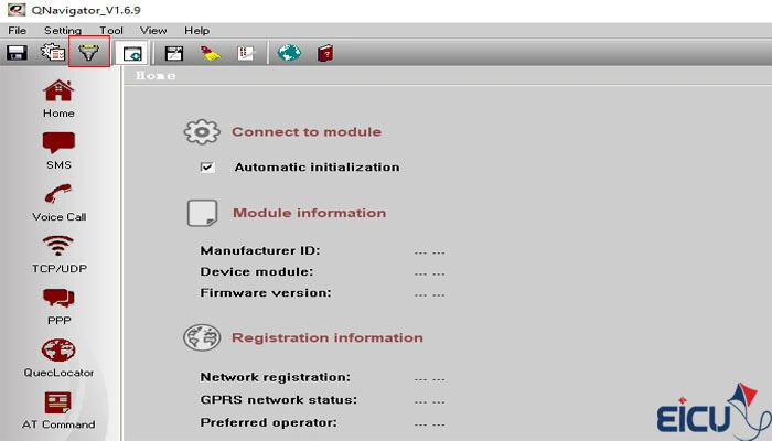
- Install the Qnavigator: Open Your Web Browser: Launch your preferred web browser (e.g., Chrome, Firefox, Safari).In the search box, type “Download QNavigator” or use this link Next
Click for Download from Quectel
After downloading QNavigator, open it and continue the software tutorial by clicking Next

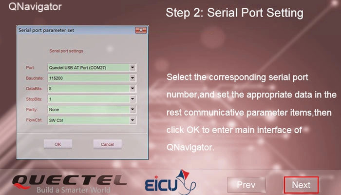
Select your communication port and set the baud rate to 115200
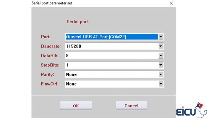
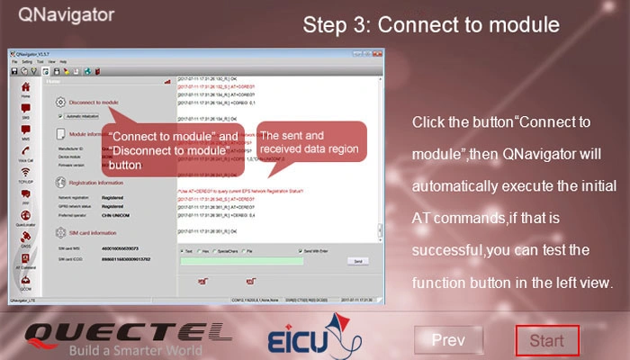
After selecting the port and setting the baud rate, follow the steps as shown in the image below:
Resource Download #
- EC200U20Windowse20Driver
- Quectel_EC200U_Series_Hardware_Design_V1_0_0_Preliminary_20210406
- Quectel_EC200U_Series_LTE_Standard_Specification_V1.1
- Quectel_EC200UEG915U_Series_AT_Commands_Manual_V1.0
- Quectel_ECx00UEGx00U_Series_GNSS_Application_Note_V1.0
- Quectel_ECx00UEGx00U_Series_GNSS_Application_Note_V1.0-1
FAQ #