DIO1568 Dual Sim Card Analog Switch, for 2FF USIM, FPC Cable support
Out of stock
- Ultra-low on-resistance: 0.85 Ω on SIM path
- 2FF Sim card Connector
- Very low power consumption
- Dual-SIM card multiplexing target application
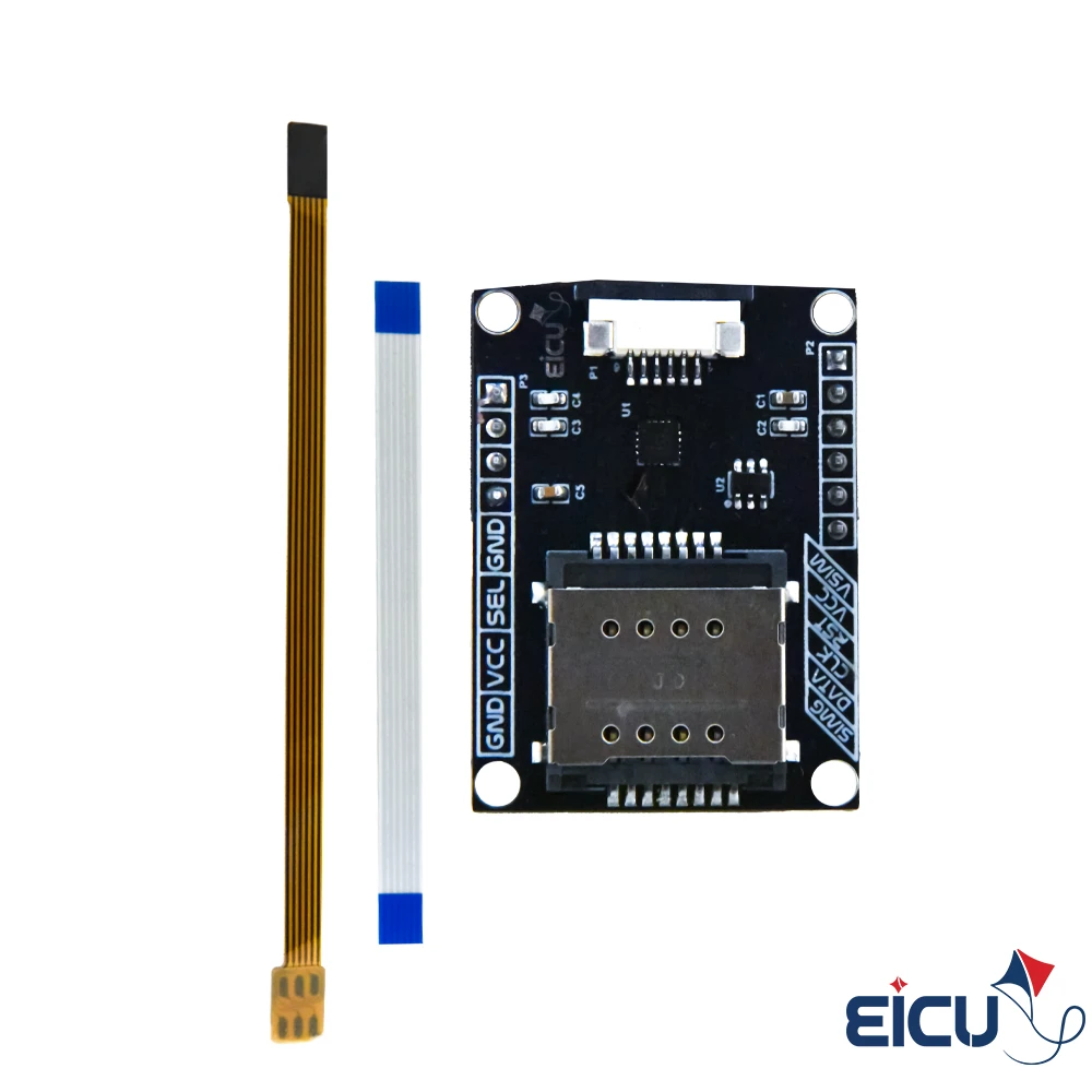
- FPC Connector & Flat
$ 4.5
Out of stock
CompareDIO1568 Dual Sim Card Analog Switch Description
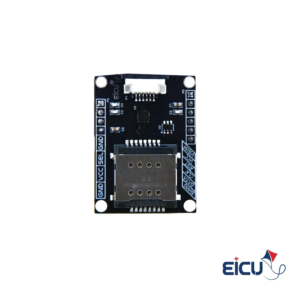
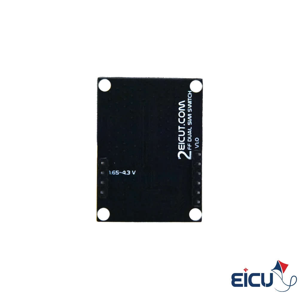
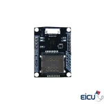
The DIO1568 Evaluation Board (EVB) lets you quickly evaluate and prototype with the DIO1568 low-power, dual-SIM analog switch. The DIO1568 is a quad SPDT analog switch optimized for dual-SIM card multiplexing, operating from a single 1.65 V to 5.5 V supply. It offers ultra-low on-resistance (0.85 Ω on the SIM path) and fast, break-before-make switching thanks to sub-micron CMOS fabrication. The device also maintains very low quiescent current even when control voltage is below VCC, enabling direct interfacing with baseband processor GPIOs in mobile handsets. Two compact QFN package options are available: QFN1.8×2.6-16 and QFN3×3-16.
DIO1568 Dual Sim Card Analog Switch Features
- Switch type: Quad SPDT (4×)
- Supply voltage: 1.65 V to 5.5 V
- Low on-resistance: 0.85 Ω (SIM path); 2.7 Ω (other paths)
- Capacitance: 20 pF CON at DAT/CLK/RST path
- Low quiescent power consumption (suitable for battery-powered devices)
- Package options: 16‑lead QFN 1.8×2.6 mm and 16‑lead QFN 3×3 mm
DIO1568 Dual Sim Card Analog Switch Specifications
- Topology: 4× SPDT analog switch
- Operating voltage range: 1.65–5.5 V
- On-resistance: 0.85 Ω (SIM path) / 2.7 Ω (other paths)
- Input/output capacitance: ~20 pF on DAT/CLK/RST lines
- Control: Designed for break-before-make operation
- Quiescent current: Very low, remains low when control voltage < VCC
- Packages: QFN1.8×2.6-16, QFN3×3-16
DIO1568 Dual Sim Card Analog Switch Applications
- Cell phones and PDAs (dual-SIM designs)
- Set-top boxes
- Digital cameras
- Notebooks and laptops
- TV / LCD monitors
DIO1568 Dual Sim Card Analog Switch Dimensions
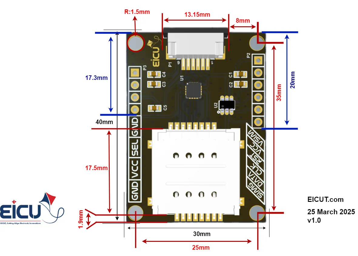
Downloads
Based on 0 reviews
Be the first to review “DIO1568 Dual Sim Card Analog Switch, for 2FF USIM, FPC Cable support”
You must be logged in to post a review.
| Topology | 4× SPDT analog switch |
|---|---|
| Operating voltage range | 1.65–5.5 V |
| Quiescent current | Very low, remains low when control voltage < VCC |
| On-resistance | 0.85 Ω (SIM path) / 2.7 Ω (other paths) |
| Input/output capacitance | ~20 pF on DAT/CLK/RST lines |
| Packages | QFN1.8×2.6-16, QFN3×3-16 |


There are no reviews yet.