

E70G Mini DB
Basic Overview #
The E70G Mini DB Is a compact and integrated module designed specifically to be used on products and save a lot of time handling GSM & GNSS power, RF circuits and etc.
Supported Module List #
The pin of this board are standard breadboard bases.
Feature List #
- Class 3 (23dBm±2.7dB) for FDD-LTE bands
- Class 3 (23dBm±2.7dB) for TDD-LTE bands
- Maximum support CAT1 Bis
- Support 1.4 ~ 20MHz RF bandwidth
- FDD: Maximum uplink rate 5Mbps, maximum downlink rate 10Mbps
- TDD: Maximum uplink rate 2Mbps, maximum downlink rate 8Mbps
- Support Wi-Fi Scan positioning, share the main antenna
- TCP/UDP/MQTT/FTP/FTPS/HTTP/HTTPS/LWM2M/Coap
- For audio use, requires an external codec chip
- Supports 16-bit linear encoding format
- Supports short frame mode: the module is only used as a master device
Board Resources #
Function Description #
The detailed assignment of the peripheral interfaces on the Development board is as follows:
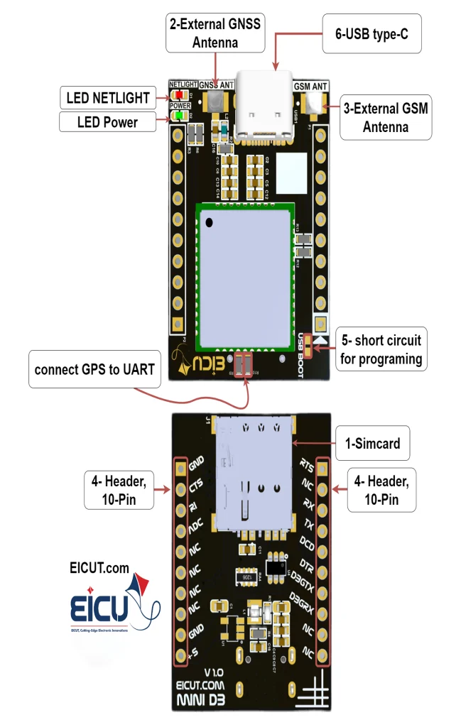
| NO. | Name | Silkscreen | Comment |
|---|---|---|---|
| 1 | Sim card case | J1 | 4FF SIM Card 12.3 × 8 mm |
| 2 | External GNSS Antenna | GNSS ANT | UFL ANTENNA |
| 3 | External GSM Antenna | GSM ANT | Main antenna + Wi-Fi antenna |
| 4 | 10pin | P1-P2 | header 2.54mm |
| 5 | Jumper | USB BOOT | Short circuit to program the module |
| 6 | USB TYPE-C | USB1 | USB interface which can be used for debugging and upgrading firmware |
The Development board has 2 functional indication LEDs, as follows:
- D1: NETLIGHT
- D2: Power indication LED
Board Interfaces #
The main pin placement of the Development board is shown in the following figure:
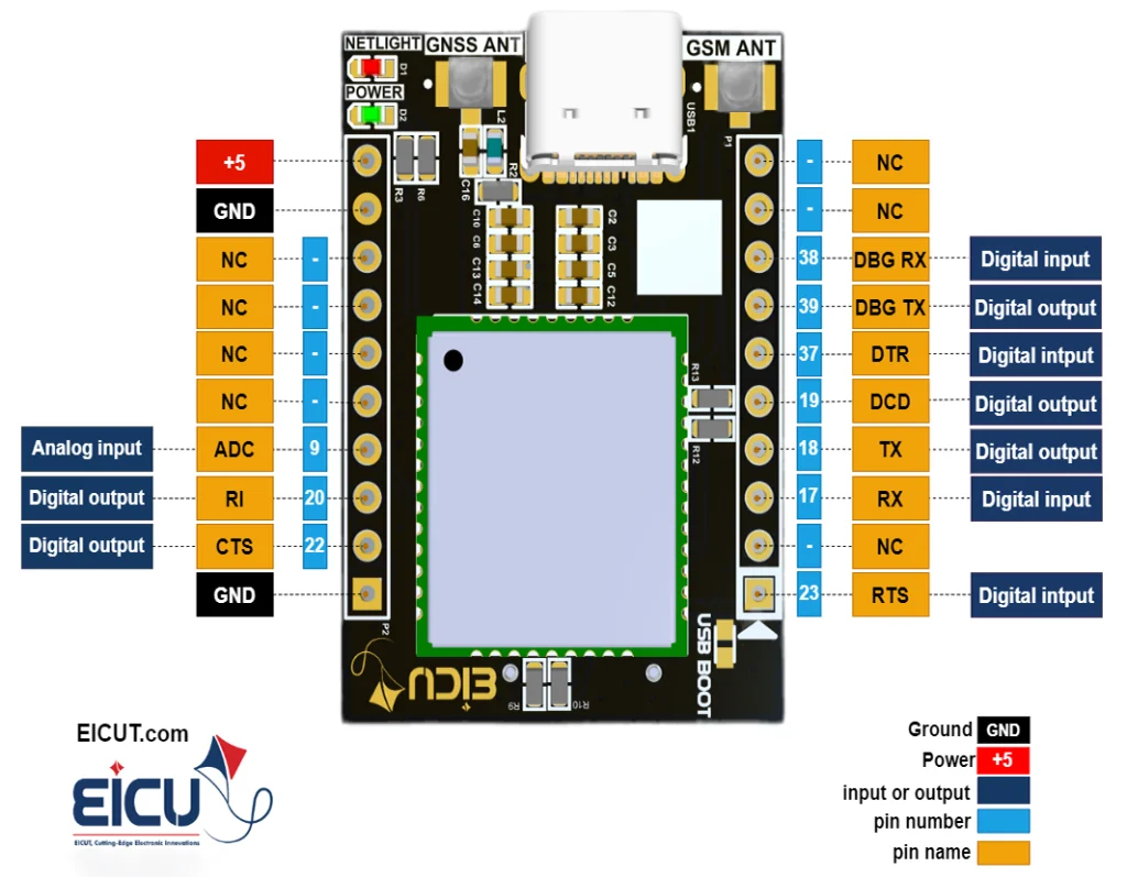
- E70 Mini DB P1-P2
| NO. | Name | Silkscreen | Comment |
|---|---|---|---|
| P1-1 | Request to Send | RTS | Output and input |
| P1-2 | NC | NC | Not connect |
| P1-3 | RXD | RXD | Receive data |
| P1-4 | TXD | TXD | Transmit data |
| P1-5 | DCD | DCD | Digital output |
| P1-6 | DTR | DTR | Digital input |
| P1-7 | DBG-TXD | DBGTX | Transmit data |
| P1-8 | DBG-RXD | DBGRX | Receive data |
| P1-9 | NC | NC | Not connect |
| P1-10 | NC | NC | Not connect |
| P2-1 | Ground | GND | Ground |
| P2-2 | CTS | CTS | Clear to send |
| P2-3 | RI | RI | Ring indication |
| P2-4 | ADC0 | ADC | General purpose analog to digital converter Vmax=2.8V, Vmin=0V |
| P2-5 | NC | NC | Not connect |
| P2-6 | NC | NC | Not connect |
| P2-7 | NC | NC | Not connect |
| P2-8 | NC | NC | Not connect |
| P2-9 | Ground | GND | Ground |
| P2-10 | Power | +5 | Main power supply of module Make sure supply sufficient current in a transmitting burst (typically rises to 1.6A) Vmin=4.5V, Vmax=5.5V |
🔗VRTC Pin Voltage
• Input: VImax = 3.3V, VImin = 1.5V, VInorm = 2.8V
• Output: VOmax = 3V, VOmin = 2V, VOnorm = 2.8V
• IOmax = 2mA
• Iin ≈ 10µA
Board Dimensions #
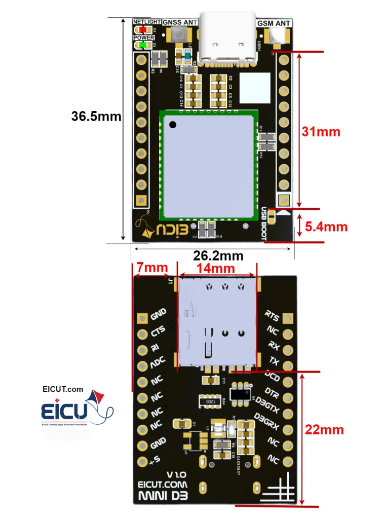
🔗Hint
Make sure the power supply voltage is stable.
The board should power up and turn on automatically without the need for a turn-on function.
FAQ #
Updated on July 22, 2026