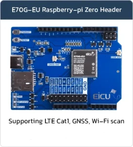

E70x UNO Arduino Header
Basic Overview #
The Arduino LTE HAT is a compact cellular expansion board (shield) designed for Arduino platforms. It integrates a Eicut E70x series module to provide reliable 4G LTE connectivity without needing complex external RF design, SIM circuitry, or power management.
This HAT enables easy IoT and M2M applications by adding LTE data communication (up to 10 Mbps downlink / 5 Mbps uplink in FDD mode), along with support for protocols like TCP/UDP, MQTT, HTTP/HTTPS, and more. It includes a Nano SIM slot, USB Type-C interface, GNSS antenna support, and a 2×9 pin header for additional signals.
The board is fully compatible with popular Arduino boards such as UNO R3/R4, Leonardo, Zero, and Yun Rev2. All logic pins operate at 1.8V (level shifting required for 3.3V/5V systems). It is ideal for projects needing wireless internet, remote monitoring, or cloud connectivity in areas without Wi-Fi.
Supported Module List #
- Arduino UNO R3
- Arduino UNO Q
- Arduino UNO R3 SMD
- Arduino Zero
- Arduino Yun Rev2
- Arduino UNO Wi-Fi Rev2
- Arduino UNO R4 Wi-Fi
- Arduino UNO R4 Minima
- Arduino Leonardo
Feature List #
- Class 3 (23dBm±2.7dB) for FDD-LTE bands
- Class 3 (23dBm±2.7dB) for TDD-LTE bands
- Maximum support CAT1 Bis
- Support 1.4 ~ 20MHz RF bandwidth
- FDD: Maximum uplink rate 5Mbps, maximum downlink rate 10Mbps
- TDD: Maximum uplink rate 2Mbps, maximum downlink rate 8Mbps
- Support Wi-Fi Scan positioning, share the main antenna
- TCP/UDP/MQTT/FTP/FTPS/HTTP/HTTPS/LWM2M/Coap
- For audio use, requires an external codec chip
- Supports 16-bit linear encoding format
- Supports short frame mode: the module is only used as a master device
Board Resources #
Function Description #
The detailed assignment of the peripheral interfaces on the Arduino HAT board is as follows:
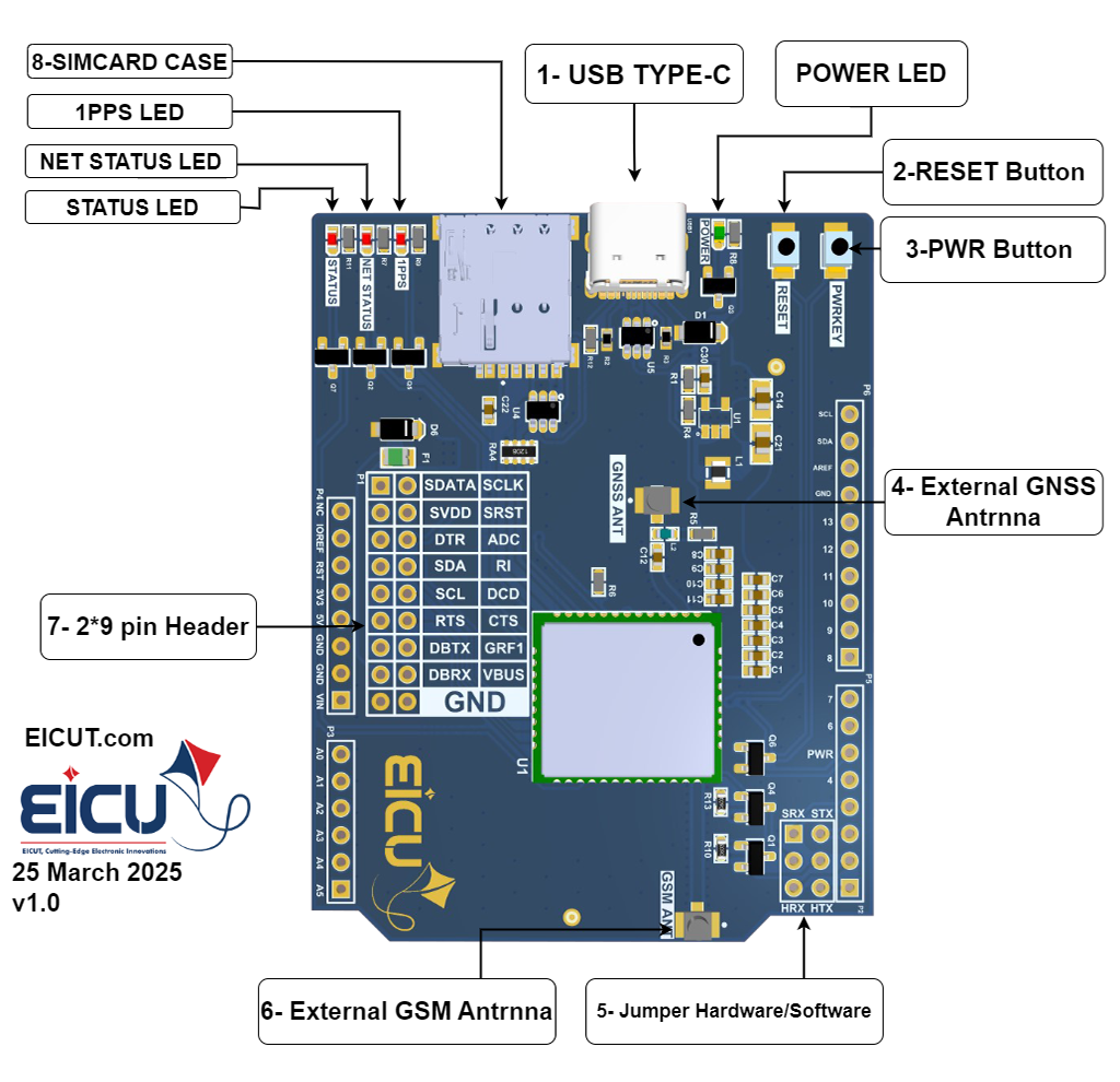
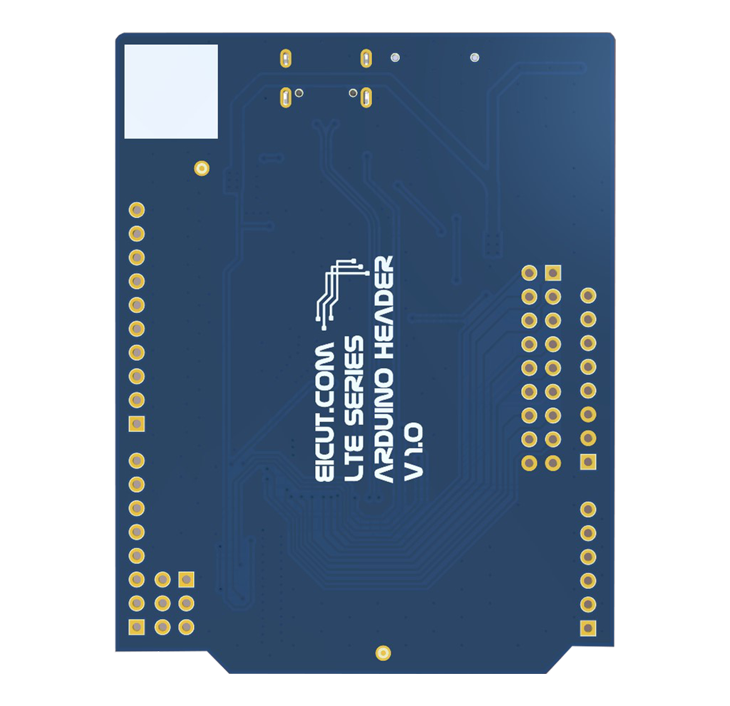
| NO. | Name | Silkscreen | Comment |
|---|---|---|---|
| 1 | USB Type-C Interface | USB1 | – |
| 2 | Reset button | RESET | push button |
| 3 | PWR button | PWRKEY | push button |
| 4 | External LORA Antenna | GNSS ANT | UFL ANTENNA |
| 5 | Jumper hardware/software | P2 | 2*3 pin 2.54 |
| 6 | External GNSS Antenna | GNSS ANT | UFL ANTENNA |
| 7 | Pin header 2*9 pin | P1 | 2*9 pin 2.54 |
| 8 | SIMCARD CASE | J1 | 4ff (Nano SIM) |
The Arduino HAT board has 4 functional indication LEDs, as follows:
- D2: LED Connect NETSTATUS
- D3: LED Connect POWER
- D4: LED Connect 1PPS
- D5: LED Connect STATUS
Board Interfaces #
The main pin placement of the Arduino HAT board is shown in the following figure:
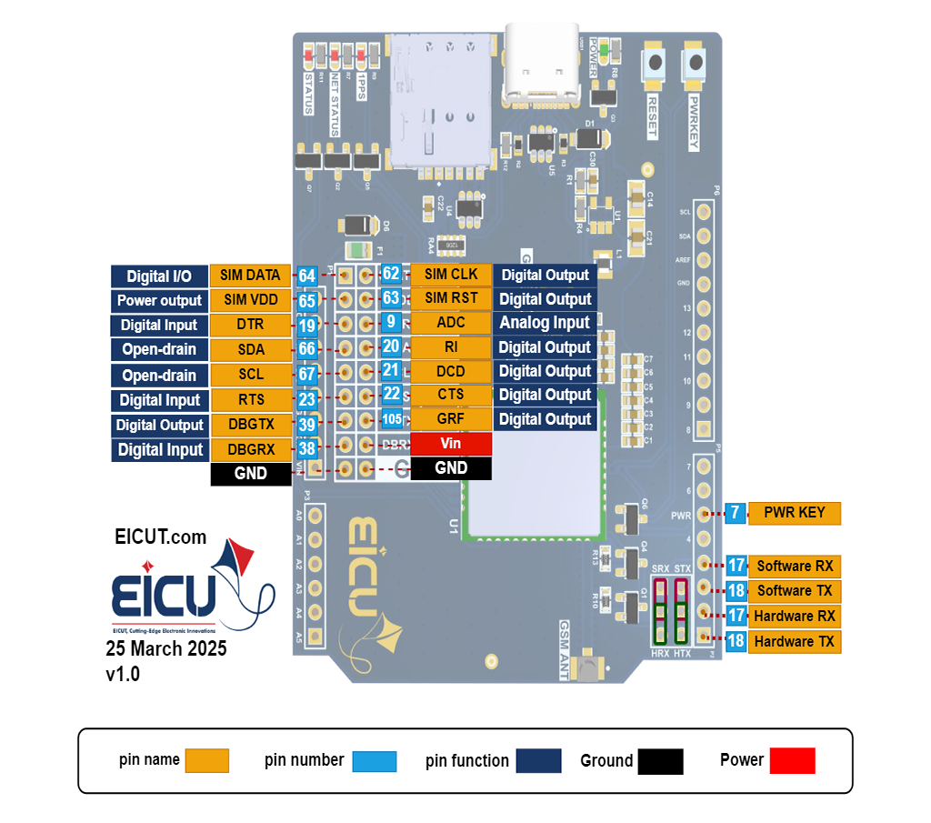
| NO. | Name | Silkscreen | Comment |
|---|---|---|---|
| 2*9-1Pin | SIM2DATA | SDATA | SIM2 card data signal line |
| 2*9-2Pin | SIM2VDD | SVVD | SIM2 card power supply |
| 2*9-3Pin | DTR | DTR | DTE is ready; otherwise, it remains suspended. |
| 2*9-4Pin | SDA | SDA | CI21 serial data signal |
| 2*9-5Pin | SCL | SCL | CI21 serial clock signal |
| 2*9-6Pin | RTS | RTS | DTE request sent |
| 2*9-7Pin | DEBUG_TXD | DBTX | DEBUG Serial Port Send |
| 2*9-8Pin | DEBUG_RXD | DBRX | DEBUG Serial Port Receive |
| 2*9-9Pin | Ground | GND | – |
| 2*9-10Pin | SIM2CLK | SCLK | SIM2 card clock signal line |
| 2*9-11Pin | SIM2RST | SRST | SIM2 card reset signal line |
| 2*9-12Pin | ADC | ADC | The input voltage detection range is 0~1.2V. When using the analog-to-digital converter interface, connect it in series with a 1kΩ pin; otherwise, leave it floating. |
| 2*9-13Pin | RI | RI | Output a ringing notification; otherwise, leave it floating. |
| 2*9-14Pin | DCD | DCD | Module output carrier detection: if not in use, leave floating. |
| 2*9-15Pin | CTS | CTS | DTE Clear Send |
| 2*9-16Pin | GRF1 | GRF1 | General Radio Frequency Control |
| 2*9-17Pin | 5+ | VBUS | Input voltage |
| 2*9-18Pin | Ground | GND | – |
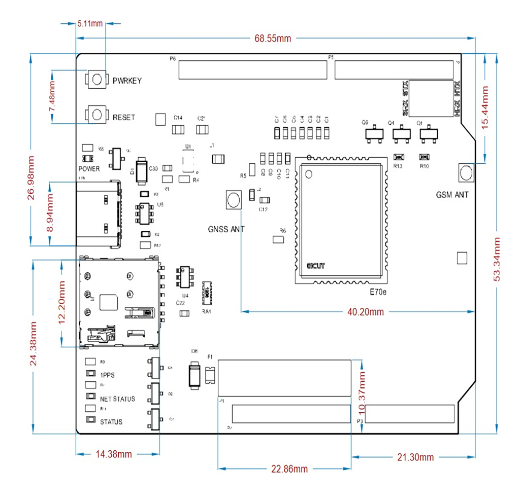
Board Dimensions #
Arduino HAT board dimensions:
Getting Started Preparation #
Step 1: Connect the Arduino hat Board
Connect the Arduino hat board to the computer’s USB port using a USB Type-C cable for power supply and data.
make sure the power supply voltage is stable.
Step 2: In the next step, install the Qnavigator software from the link below.
Step 3: After installing the software, follow the software instructions and select your board in the port section, set the baud rate to 115200, and click Connect.
FAQ #